
The Toyota 8FGU15, 8FGU18, 8FGU20, 8FGU25, 8FGU30 and 8FGU32 listing retains two main repair-manual counts, an April 2010 supplement, a parts catalog and three separately named engine manuals. Its contents distinguish chassis, engine, control and electrical subjects, followed by workshop preparation and reassembly tips.
Document Details
TOYOTA 8FGU15, 8FGU18, 8FGU20, 8FGU25, 8FGU30, 8FGU32 Forklift Repair Manual – 1389 Pages & 1867 Pages
Supplement Manual (above models as of April 2010) – 227 Pages
Parts Catalog – 166 Pages
4Y model Engine Manual – 250 Pages
4Y-E Engine Manual – 104 Pages
1DZ-II Engine Manual – 196 Pages
TOYOTA 8FGU15, 8FGU18, 8FGU20, 8FGU25, 8FGU30, 8FGU32 Forklift Repair Manual
Format: PDF
Language: English
Model Covered: 8FGU15, 8FGU18, 8FGU20, 8FGU25, 8FGU30, 8FGU32
TOYOTA 8FGU15, 8FGU18, 8FGU20, 8FGU25, 8FGU30, 8FGU32 Forklift Repair Manual – 1389 Pages & 1867 Pages
Supplement Manual (above models as of April 2010) – 227 Pages
Parts Catalog – 166 Pages
4Y model Engine Manual – 250 Pages
4Y-E Engine Manual – 104 Pages
1DZ-II Engine Manual – 196 Pages
Document Scope
This manual covers the service procedures of the TOYOTA FORKLIFT 8FGU15 – 32 series. Please use this manual for providing quick, correct servicing of the corresponding forklift model;.
This manual deals with the models realease for this forklift even those after April 2010. Please under-stand that disagreement can take place between the descriptions in the manual and actual vehicles due to change in design and specifications. Any change or modifications thereafter will be informed by Toyota Industrial Equipment Parts & Service News.
For the service procedures of the mounted engine, read repair manuals listed below as reference together with this manual.
Source Heading
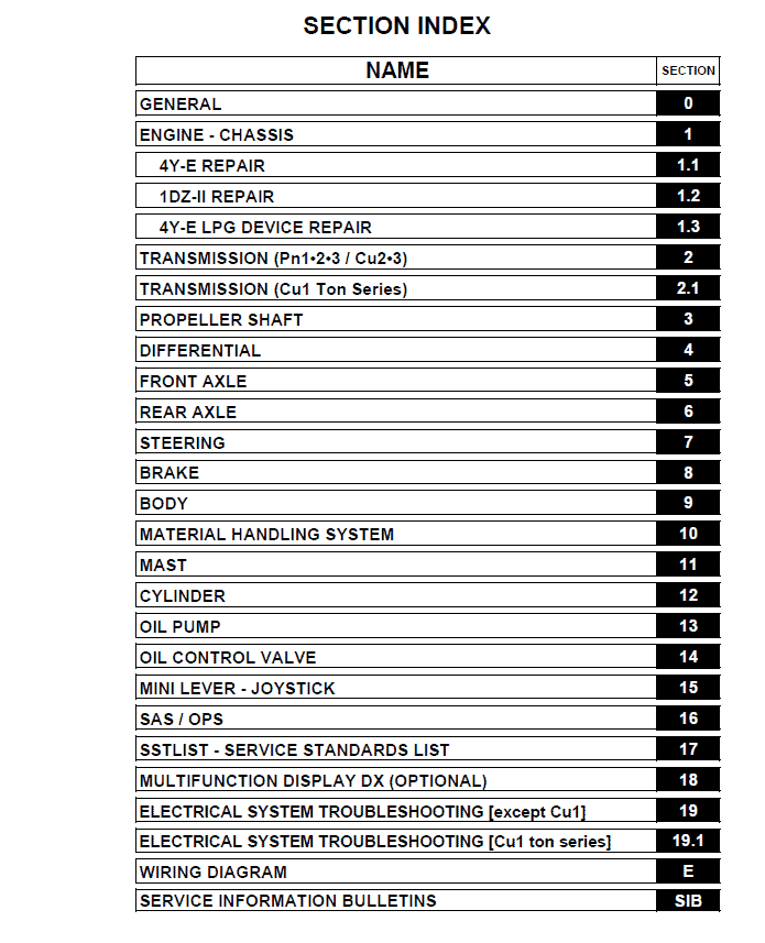
Table of content of the Repair Service Manual
Contents Listed
GENERAL
ENGINE – CHASSIS
4Y-E REPAIR
1DZ-II REPAIR
4Y-E LPG DEVICE REPAIR
TRANSMISSION (Pn1•2•3 / Cu2•3)
TRANSMISSION (Cu1 Ton Series)
PROPELLER SHAFT
DIFFERENTIAL
FRONT AXLE
REAR AXLE
STEERING
BRAKE
BODY
MATERIAL HANDLING SYSTEM
MAST
CYLINDER
OIL PUMP
OIL CONTROL VALVE
MINI LEVER – JOYSTICK
SAS / OPS
SSTLIST – SERVICE STANDARDS LIST
MULTIFUNCTION DISPLAY DX (OPTIONAL)
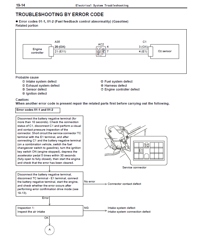
ELECTRICAL SYSTEM TROUBLESHOOTING [except Cu1]
ELECTRICAL SYSTEM TROUBLESHOOTING [Cu1 ton series]
WIRING DIAGRAM
SERVICE INFORMATION BULLETINS
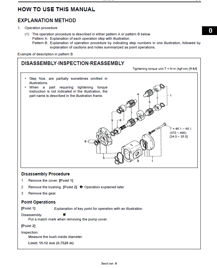
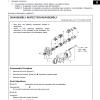
Procedure Excerpt
OPERATIONAL TIPS
2. Tactful operation
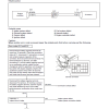
(1) Prepare the mechanic tools, necessary measuring instruments (circuit tester, megger, oil pressure gauge,
etc.) and SSTs before starting operation.
(2) Before disconnecting wiring, always check the cable color and wiring state.
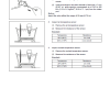
(3) When overhauling functional parts, complicated portions or related mechanisms, arrange the parts neatly to
prevent confusion.
(4) When disassembling and inspecting such a precision part as the control valve, use clean tools and operate
in a clean location.
(5) Follow the described procedures for disassembly, inspection and reassembly.
(6) Replace, gaskets, packings and O-rings with new ones each time they are disassembled.
(7) Use genuine Toyota parts for replacement.
(8) Use specified bolts and nuts. Observe the specified tightening torque at the time of reassembly.
(Tighten to the center of the specified tightening torque range.)
If no tightening torque is specified, tighten the bolt or nut according to the standard tightening torque table.
The supplement is explicitly described as covering the listed models as of April 2010. The source also notes later design changes and possible differences from individual machines; this does not certify coverage of every later edition. Separate engine manuals do not establish that every named engine fits every listed forklift model.
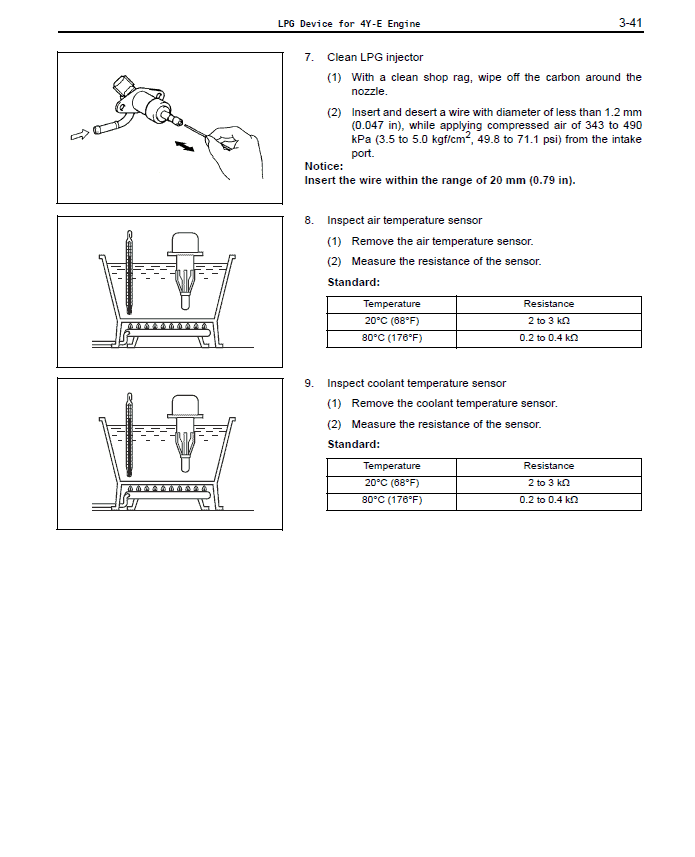
Match the listed documentation to the machine and its stated publication or serial scope. Procedure samples retain their notices and component references and should be read within the full manual section. Tools mentioned in the text are not supplied with the documentation.


Reviews
There are no reviews yet.