
THE MANUAL LIBRARY
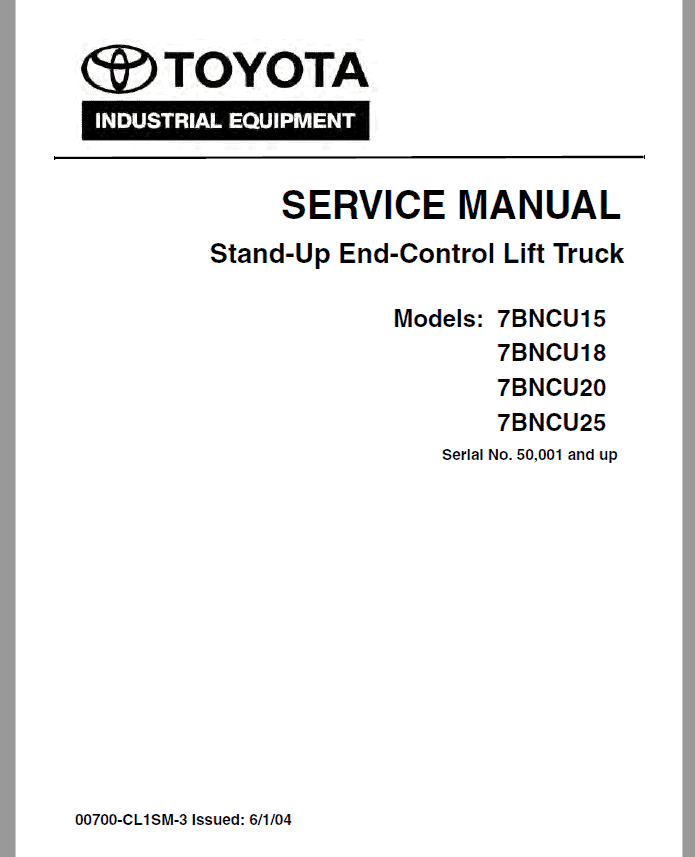
Toyota 7BNCU15, 7BNCU18, 7BNCU20, 7BNCU25 Lift Truck Repair Manual
$34.00
Documentation Specifications
| Manufacturer | Toyota |
| Applicable Model | 7BNCU15, 7BNCU18, 7BNCU20, 7BNCU25 |
| Serial Number Range | 50,001 and up |
| Machine Type | Truck |
| Documentation | Repair Manual and Electrical Schematics Manual |
| Language | English |
| Format |
Manuals Provided
| TOYOTA 7BNCU15, 7BNCU18, 7BNCU20, 7BNCU25 Lift Truck Repair Manual | 456 Pages |
| Electrical Schematics Manual | 2 Pages |
For Toyota 7BNCU15, 7BNCU18, 7BNCU20, 7BNCU25 Lift Truck, this reference brings together the listed repair manual material. Start with How to Use This Manual and follow the relevant document section for the task.
What’s Covered Inside
Serial No. 50,001 and up
TOYOTA 7BNCU15, 7BNCU18, 7BNCU20, 7BNCU25 Lift Truck Repair Manual – 456 Pages
Electrical Schematics Manual – 2 Pages
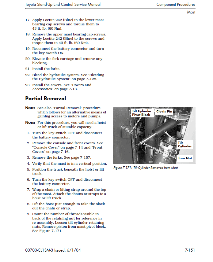
This manual covers the inspection, adjustment and repair procedures mainly for the overhaul of the engine, chassis and material handling system of the TOYOTA Stand-Up End-Control Lift Truck 7BNCU15, 7BNCU18, 7BNCU20, 7BNCU25.
For the service procedures of the mounted engine, read repair manuals listed below as reference together with this manual.
Table of content of the Repair Service Manual
How to Use This Manual . . . . . . . . . . . . . . . . . . . . . . . . . . . . . . . 1-1
Map of the Manual . . . . . . . . . . . . . . . . . . . . . . . . . . . . . . . . . . . . . . . . . 1-2
Manual Design . . . . . . . . . . . . . . . . . . . . . . . . . . . . . . . . . . . . . . . . . . . . 1-4
Abbreviations & Symbols. . . . . . . . . . . . . . . . . . . . . . . . . . . . . . . . . . . . . 1-5
Safety . . . . . . . . . . . . . . . . . . . . . . . . . . . . . . . . . . . . . . . . . . . . . 2-1
Definitions . . . . . . . . . . . . . . . . . . . . . . . . . . . . . . . . . . . . . . . . . . . . . . . 2-2
General Safety. . . . . . . . . . . . . . . . . . . . . . . . . . . . . . . . . . . . . . . . . . . . . 2-3
Battery Safety . . . . . . . . . . . . . . . . . . . . . . . . . . . . . . . . . . . . . . . . . . . . . 2-7
Static Precautions . . . . . . . . . . . . . . . . . . . . . . . . . . . . . . . . . . . . . . . . . 2-12
Jacking Safety. . . . . . . . . . . . . . . . . . . . . . . . . . . . . . . . . . . . . . . . . . . . 2-14
Towing . . . . . . . . . . . . . . . . . . . . . . . . . . . . . . . . . . . . . . . . . . . . . . . . . 2-15
Welding Safety . . . . . . . . . . . . . . . . . . . . . . . . . . . . . . . . . . . . . . . . . . . 2-16
Systems Overview. . . . . . . . . . . . . . . . . . . . . . . . . . . . . . . . . . . . 3-1
Lift Truck Dimensions and Specifications . . . . . . . . . . . . . . . . . . . . . . . . 3-2
General System Data. . . . . . . . . . . . . . . . . . . . . . . . . . . . . . . . . . . . . . . . 3-4
Configure Mode . . . . . . . . . . . . . . . . . . . . . . . . . . . . . . . . . . . . . . . . . . . . 3-6
Maintenance Mode . . . . . . . . . . . . . . . . . . . . . . . . . . . . . . . . . . . . . . . . 3-11
Software Configuration/PC Loader Program . . . . . . . . . . . . . . . . . . . . . 3-15
Planned Maintenance . . . . . . . . . . . . . . . . . . . . . . . . . . . . . . . . . 4-1
Maintenance Guidelines . . . . . . . . . . . . . . . . . . . . . . . . . . . . . . . . . . . . . 4-2
Battery Maintenance . . . . . . . . . . . . . . . . . . . . . . . . . . . . . . . . . . . . . . . 4-11
Troubleshooting . . . . . . . . . . . . . . . . . . . . . . . . . . . . . . . . . . . . .5-1
How to Use This Chapter . . . . . . . . . . . . . . . . . . . . . . . . . . . . . . . . . . . . 5-2
Start-up. . . . . . . . . . . . . . . . . . . . . . . . . . . . . . . . . . . . . . . . . . . . . . . . . 5-3
Power Amplifier Fault Codes . . . . . . . . . . . . . . . . . . . . . . . . . . . . . . . . . 5-5
Electrical Troubleshooting Guidelines . . . . . . . . . . . . . . . . . . . . . . . . . . 5-9
Troubleshooting Wiring Problems. . . . . . . . . . . . . . . . . . . . . . . . . . . . . 5-19
Hydraulic Troubleshooting Guidelines . . . . . . . . . . . . . . . . . . . . . . . . . 5-26
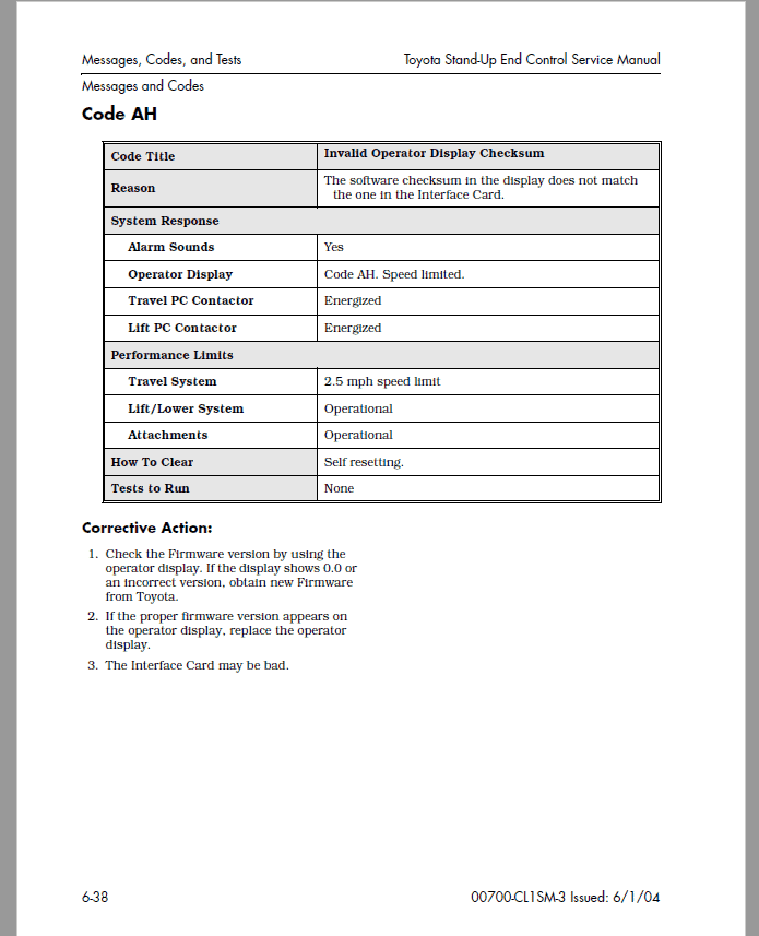
Messages, Codes, and Tests . . . . . . . . . . . . . . . . . . . . . . . . . . . .6-1
List of Codes and Tests . . . . . . . . . . . . . . . . . . . . . . . . . . . . . . . . . . . . . 6-2
Message and Code Summary Tables. . . . . . . . . . . . . . . . . . . . . . . . . . . . 6-5
Messages and Codes . . . . . . . . . . . . . . . . . . . . . . . . . . . . . . . . . . . . . . 6-11
Analog Tests . . . . . . . . . . . . . . . . . . . . . . . . . . . . . . . . . . . . . . . . . . . . 6-83
Input Tests . . . . . . . . . . . . . . . . . . . . . . . . . . . . . . . . . . . . . . . . . . . . . 6-89
Output Tests . . . . . . . . . . . . . . . . . . . . . . . . . . . . . . . . . . . . . . . . . . . .6-121
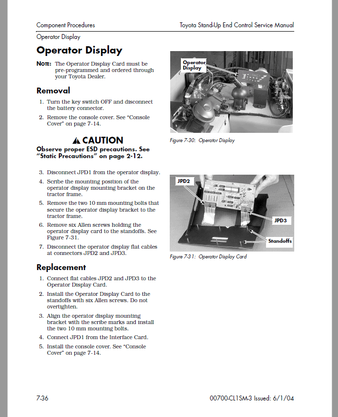
Component Procedures. . . . . . . . . . . . . . . . . . . . . . . . . . . . . . . .7-1
Component Locator Photos . . . . . . . . . . . . . . . . . . . . . . . . . . . . . . . . . . 7-5
Covers and Accessories . . . . . . . . . . . . . . . . . . . . . . . . . . . . . . . . . . . . 7-13
Steering and Controls . . . . . . . . . . . . . . . . . . . . . . . . . . . . . . . . . . . . . 7-23
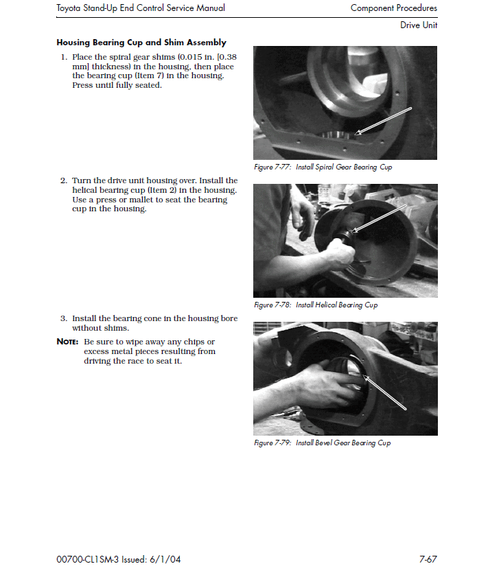
Drive and Brake. . . . . . . . . . . . . . . . . . . . . . . . . . . . . . . . . . . . . . . . . . 7-45
Electrical Components . . . . . . . . . . . . . . . . . . . . . . . . . . . . . . . . . . . . . 7-81
Hydraulic Components. . . . . . . . . . . . . . . . . . . . . . . . . . . . . . . . . . . . .7-125
Mast, Chain, Hose, Cable . . . . . . . . . . . . . . . . . . . . . . . . . . . . . . . . . . .7-147
Theory of Operation . . . . . . . . . . . . . . . . . . . . . . . . . . . . . . . . . .8-1
Traction System . . . . . . . . . . . . . . . . . . . . . . . . . . . . . . . . . . . . . . . . . . . 8-2
Travel Functions . . . . . . . . . . . . . . . . . . . . . . . . . . . . . . . . . . . . . . . . . . 8-9
Hydraulic Functions . . . . . . . . . . . . . . . . . . . . . . . . . . . . . . . . . . . . . . 8-20
Sideshift . . . . . . . . . . . . . . . . . . . . . . . . . . . . . . . . . . . . . . . . . . . . . . . 8-30
Steering . . . . . . . . . . . . . . . . . . . . . . . . . . . . . . . . . . . . . . . . . . . . . . . . 8-34
Sense Wires . . . . . . . . . . . . . . . . . . . . . . . . . . . . . . . . . . . . . . . . . . . . . 8-36
Appendix . . . . . . . . . . . . . . . . . . . . . . . . . . . . . . . . . . . . . . . . . .A-1
Lubrication Equivalency Chart . . . . . . . . . . . . . . . . . . . . . . . . . . . . . . . .A-2
Torque Chart – Standard (Ferrous) . . . . . . . . . . . . . . . . . . . . . . . . . . . . .A-4
Torque Chart – Metric . . . . . . . . . . . . . . . . . . . . . . . . . . . . . . . . . . . . . . .A-5
Torque Chart – Standard (Brass) . . . . . . . . . . . . . . . . . . . . . . . . . . . . . . .A-6
Decimal Equivalent Chart . . . . . . . . . . . . . . . . . . . . . . . . . . . . . . . . . . . .A-7
Standard/Metric Conversions . . . . . . . . . . . . . . . . . . . . . . . . . . . . . . . . .A-9
Schematics . . . . . . . . . . . . . . . . . . . . . . . . . . . . . . . . . . . . . . . . . . . . . . A-11
Index . . . . . . . . . . . . . . . . . . . . . . . . . . . . . . . . . . . . . . . . . . . . . I-1
Check 50,001 and up against the machine identification before using this repair manual. Refer to How to Use This Manual within its stated document and equipment scope.
Reviews
There are no reviews yet.