
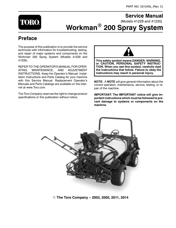
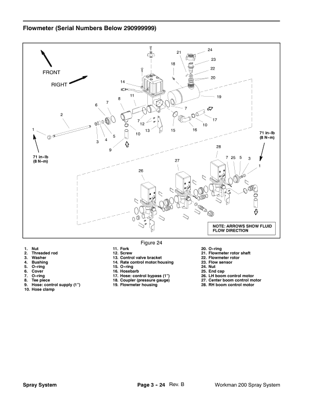
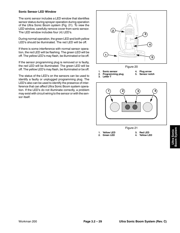
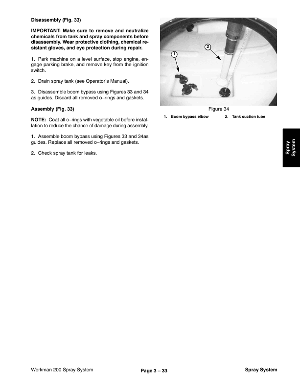
THE MANUAL LIBRARY
Toro Workman Spray System Service Repair Manual
$30.00
Documentation Specifications
| Manufacturer | Toro |
| Applicable Model | Workman Spray System |
| Machine Type | Vehicles |
| Documentation | Repair Manual |
| Publication Reference | 03124SL |
| Language | English |
| Format |
Manuals Provided
| Repair Manual | 159 Pages |
For Toro Workman Spray System, this reference brings together the listed repair manual material. Start with 1 – Safety and Product Records and follow the relevant document section for the task.
What’s Covered Inside
Table of Content – Workman Spray System
Preface
1 – Safety and Product Records
Safety Instructions
Before Operating
While Operating
Maintenance and Service
Safety and Instruction Decals
Product Records
2 – Electrical System
Special Tools
Component Testing
Master Boom Switch
Rate Control and Boom Actuator Switches
Supervisor Key Switch
Boom Control and Monitor Power Switches
Hold and Boom Actuator (Machines with Serial Numbers Above 260000000) RelaysRelay
Traction Speed Sensor
3 – Spray System
Specifications
General Information
Precautions Concerning Chemicals Used in Spray System
Precautions for Removing or Adjusting Spray System Components
O-Ring Seal Kit (Serial Numbers Below 310000000)
Spray System Flow Diagram
Spray System Operation
Troubleshooting
Service and Repairs
Suction Dampener
Pressure Dampener
Spray Pump
Spray Pump Service
Agitation Control Valve
Agitation Nozzles (Tank mounted)
Pressure Relief Valve (Tank Mounted)
Spray Control (S.N Below 290999999)
Spray Control (S.N Above 310000000)
Flowmeter (S.N Below 290999999)
Flowmeter (S.N Above 310000000)
Rate Control Motor (S.N Below 290999999)
Regulating Valve Assembly (S.N Above 310000000)
Boom Valve Motor (S.N Below 290999999)
Boom Valve Manifold Assembly (S.N Above 310000000)
Boom Bypass
Tank Suction
Tank Drain
Turret Bodies
Turret Body Service
Boom Frame Breakaway Pivot Assembly (S.N Below 260000000)
Boom Hinge (S.N Above 260000000)
Boom Actuator (Optional) (S.N Below 260000000)
Boom Actuator Service (S.N Below 260000000)
Boom Actuator (S.N Above 260000000)
Boom Actuator Service (S.N Above 260000000)
3.1 – Sonic Boom System (Optional Kit)
General Information
Installation Instructions
Precautions Concerning Chemicals Used in Spray System
Precautions for Removing or Adjusting Spray System Components
Special Tools
Electrical Schematic
Sonic Boom System Operation
Sprayer Operation on Level Turf
Downward Slope in Turf Encountered
Rise in Turf Encountered
Boom Level Changed by Operator During Automatic Operation
Manual Boom Operation
Troubleshooting
Sonic Boom Light
Sonic Boom Calibration
Diagnostic Display
Troubleshooting Chart
Service and Repairs
Sonic Mode Switch
Relays
Electronic Control Unit (ECU)
Sonic Sensor
3.2 – Ultra Sonic Boom System (Optional Kit)
General Information
Installation Instructions
Precautions Concerning Chemicals Used in Spray System
Precautions for Removing or Adjusting Spray System Components
Special Tools
Electrical Schematic
Ultra Sonic Boom System Operation
Sprayer Operation on Level Turf
Downward Slope in Turf Encountered
Rise in Turf Encountered
Boom Level Changed by Operator
Manual Boom Operation
Troubleshooting
Sonic Boom Light
Ultra Sonic Boom Calibration
Diagnostic Lamp
Diagnostic Display
Troubleshooting Chart
Service and Repairs
Sonic Boom Fuses
Sonic Boom Switch
Sonic Sensors
Relays
Toro Electronic Controller (TEC)
4 – Electrical Diagrams
Electrical Schematic (S.N Below 260000000)
Electrical Schematic (S.N Above 260000000)
Spray System Wire Harness (S.N Below 260000000
Spray System Wire Harness (S.N From 260000001 to 280000200)
Spray System Wire Harness (S.N From 280000201 to 290999999)
Spray System Wire Harness (S.N Above 310000000)
Spray Console Wire Harness (S.N Below 260000000)
Spray Console Wire Harness (S.N From 260000001 to 260999999)
Spray Console Wire Harness (S.N From 270000001 to 290999999)
Spray Console Wire Harness (S.N Above 310000000)
Sprayer Power Harness (S.N Below 260000000)
Sprayer Power Harness (S.N Above 260000000)
Use publication 03124SL with the Workman Spray System model details to select the appropriate documentation. Refer to 1 – Safety and Product Records within its stated document and equipment scope.
Reviews
There are no reviews yet.