
THE MANUAL LIBRARY
Toro ProLine H800 (Model 31050, 31050TE, 31051) Service Repair Manual
$34.00
Documentation Specifications
| Manufacturer | Toro |
| Applicable Model | ProLine H800 (Model 31050, 31050TE, 31051) |
| Machine Type | Rotary Mowers |
| Documentation | Repair Manual |
| Publication Reference | 19241SL |
| Language | English |
| Format |
Manuals Provided
| Repair Manual | 348 Pages |
For Toro ProLine H800 (Model 31050, 31050TE, 31051), this reference brings together the listed repair manual material. Start with Service Procedure Icons and follow the relevant document section for the task.
What’s Covered Inside
Table of Content – ProLine H800 (Model 31050, 31050TE, 31051)
Title Page
Revision History
Reader Comments
Preface
Service Procedure Icons
Chapter 1 : Safety
Safety Instructions
Supervisor’s Responsibilities
Before Operating the Machine
While Operating the Machine
Maintenance and Service
Jacking Instructions
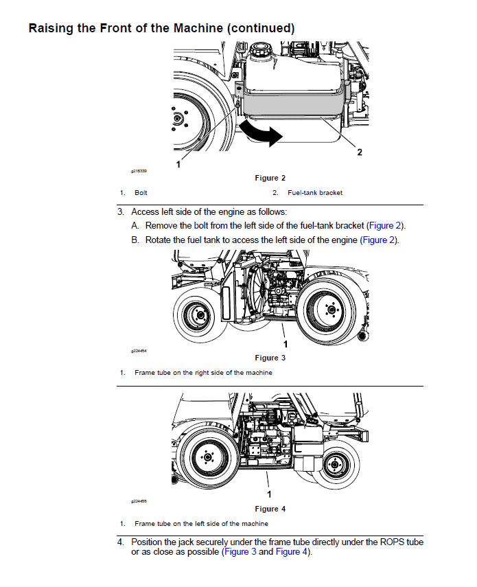
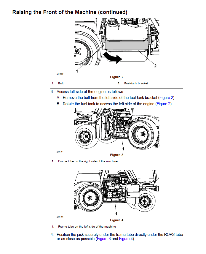
Raising the Front of the Machine
Raising the Rear of the Machine
Safety and Instructional Decals
Chapter 2 : Specifications and Maintenance
Specifications
Overall Dimensions
Engine – ProLine H800 (for Model 31050)
Engine – ProLine H800 (for Model 31050TE and 31051)
Hydraulic System
Chassis
Torque Specifications
Identifying the Fastener
Calculating the Torque Values When Using a Drive-Adapter Wrench
Standard Torque for Dry, Zinc Plated, and Steel Fasteners (Inch)
Standard Torque for Dry, Zinc Plated, and Steel Fasteners (Metric Fasteners)
Other Torque Specifications
Conversion Factors
Shop Supplies
Special Tools
Chapter 3 : Troubleshooting
GEARS – The Systematic Approach to Defining, Diagnosing and Solving Problems
General Hydraulic System Problems
Steering Circuit Problems
The Height Of Cut Circuit Problems
The Cutting Deck Lift Circuit Problems
The Hopper Lift Circuit
The Hopper Tilt Circuit
Chapter 4 : Engine
General Information
Traction Unit Operator’s Manual
Yanmar Service Repair Manuals
Service and Repairs
Air Cleaner Assembly
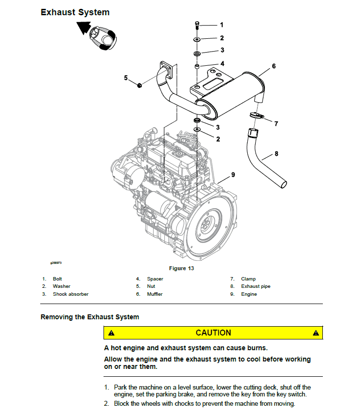
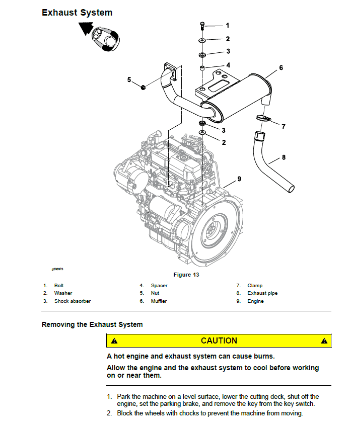
Exhaust System
Radiator
Fuel System
Engine
Yanmar 3TNV76 Service Repair Manual
Yanmar 3TNV80F Service Repair Manual
Chapter 5 : Hydraulic System
General Information
Checking the Hydraulic Fluid
Pushing or Towing the Traction Unit
Releasing Pressure from the Hydraulic System
Traction Circuit Component Failure
Hydraulic Hoses
Installing the Hydraulic Hoses and Tubes
Installing the Hydraulic Fittings
Hydraulic Schematic
Hydraulic Flow Diagrams
Traction Circuit
Steering Circuit
Height Of Cut Circuit
Auxiliary Control Circuit
Testing the Hydraulic System
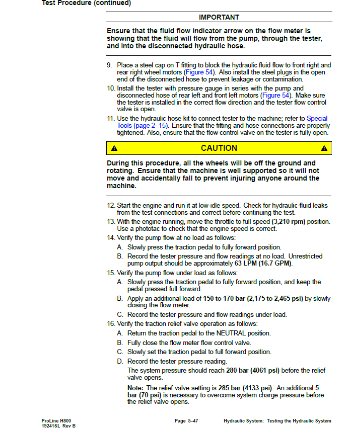
Testing the Traction Circuit – Charge Pressure
Testing the Wheel Motors Efficiency
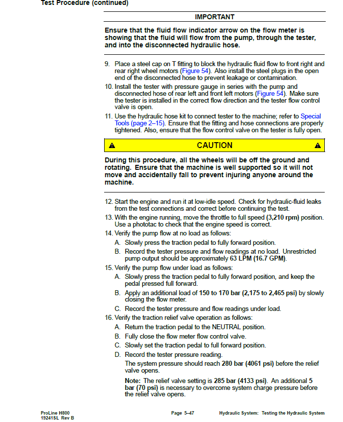
Testing the Traction Circuit – Hydraulic Pump Flow and Relief Pressure
Testing the Steering Circuit – Steering Control Valve, Relief Valve Pressure and Steering Cylinder
Testing the Steering Circuit – Charge Pump Flow
Testing the Auxiliary Control Circuit – Cutting Deck Lift Cylinder Internal Leakage
Testing the Auxiliary Control Circuit – Hopper Lift Cylinder Internal Leakage
Testing the Auxiliary Control Circuit – Hopper Tilt Cylinder Internal Leakage
Testing the Height Of Cut Cylinder Internal Leakage
Service and Repairs
General Precautions for Removing and Installing the Hydraulic System Components
Checking the Hydraulic Lines and Hoses
Flushing the Hydraulic System
Filtering the Closed-Loop Traction Circuit
Priming the Hydraulic Pump
Charging the Hydraulic System
Hydraulic Tank
Auxiliary Control Valve
Traction Neutral Arm Assembly
Hydraulic Pump Assembly
Servicing the Hydraulic Piston Pump
Servicing the Gear Pump
Front Wheel Motors
Rear Wheel Motors
Servicing the Hydraulic Wheel Motor
Differential Valve
Height Of Cut Valve
Lift Cylinder
Steering Control Valve
Steering Cylinder
Hopper Lift Cylinder
Hopper Tilt Cylinder
Height Of Cut Cylinder
Chute Cleaning Cylinder
Oil Cooler
Danfoss DDC20 Axial Piston Pump Service Repair Manual
Parker Torqmotor Service Procedure (TF, TG, TH, and TL Series)
Chapter 6 : Electrical System
General Information
Electrical Schematics and Wire Harness Drawings, Diagrams
Electronic Control Unit (ECU)
Electrical System Quick Checks
Testing the Battery (Open Circuit Test)
Testing the Charging System
Testing the Glow Plug System
Checking the Operation of the Interlock Switches
Testing the Electrical Components
Fuses
Key Switch
PTO Switch
Hazard Light Switch
Differential Lock Switch
Radiator Fan Reversal Switch
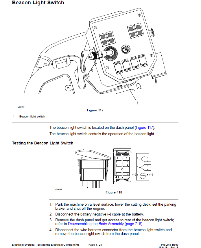
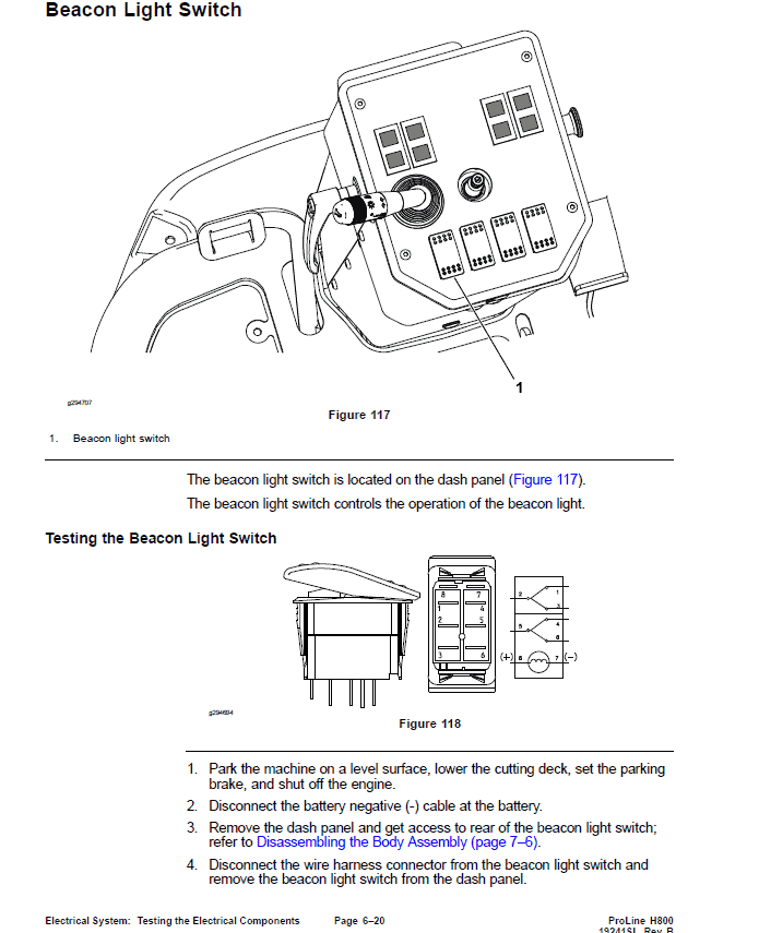
Beacon Light Switch
Indicator Lights
Height Of Cut Switch
Seat Switch
Hour Meter
Traction Neutral Switch
Traction Reverse Switch
Parking Brake Switch
Oil Pressure Switch
PTO Electric Clutch
Fuel Stop Solenoid
Relays
Diode Assembly
Slope Sensor (Optional)
Service and Repairs
Battery Storage
Battery Care
Servicing the Battery
Chapter 7 : Chassis
General Information
Service and Repairs
Wheels
Body Assembly
Steering Column
Lift Arms
Traction Pedal
Brake Pedal
Operator Seat
Servicing the Operator Seat
Frame Assembly
Grammer Seats Repair Manual
Chapter 8 : Axle and PTO
General Information
Service and Repairs
Servicing the Brake
Rear Axle assembly
Servicing the Rear Axle
Steering Spindle
PTO Drive Belt
Electric Clutch
PTO Driveshaft
Servicing the Driveshaft
PTO Shaft Assembly
Servicing the PTO Shaft Assembly
Servicing the Gearbox Assembly
Chapter 9 : Hopper Assembly
General Information
Service and Repairs
Hopper Assembly
Hopper Frame Assembly
Hopper
Hopper Lift Frame Assembly
Chute Assembly
Chapter 10 : Cutting Unit
General Information
Service and Repairs
Idler Assembly
Blade Spindle
Servicing the Blade Spindle
Caster Wheel and Flat Frame Assembly
Cutting Deck Rollers and Skids
Height Of Cut Linkage
Cutting Deck Covers
Appendix A: Foldout Drawings
Electrical Drawing Designations
Hydraulic Schematic
Electrical Schematic – Main
Electrical Schematic – Lights
Wire Harness Diagram – Main
Wire Harness Diagram – Lights
Wire Harness – Slope Sensor (Optional)
Use publication 19241SL with the ProLine H800 (Model 31050, 31050TE, 31051) model details to select the appropriate documentation. Refer to Service Procedure Icons within its stated document and equipment scope.
Reviews
There are no reviews yet.