
THE MANUAL LIBRARY
Toro Groundsmaster 7210 (Tier4) (with Yanmar Engine) Service Repair Manual
$34.00
Documentation Specifications
| Manufacturer | Toro |
| Applicable Model | Groundsmaster 7210 (Tier4) (with Yanmar Engine) |
| Machine Type | Rotary Mowers |
| Documentation | Engine Manual |
| Publication Reference | 16222SL |
| Language | English |
| Format |
Manuals Provided
| Engine Manual | 346 Pages |
For Toro Groundsmaster 7210 (Tier4) (with Yanmar Engine), this reference brings together the listed repair manual material. Start with NOTES: and follow the relevant document section for the task.
What’s Covered Inside
Table of Content – Groundsmaster 7210 (Tier4) (with Yanmar Engine)
Title Page
Revision History
Reader Comments
NOTES:
Preface
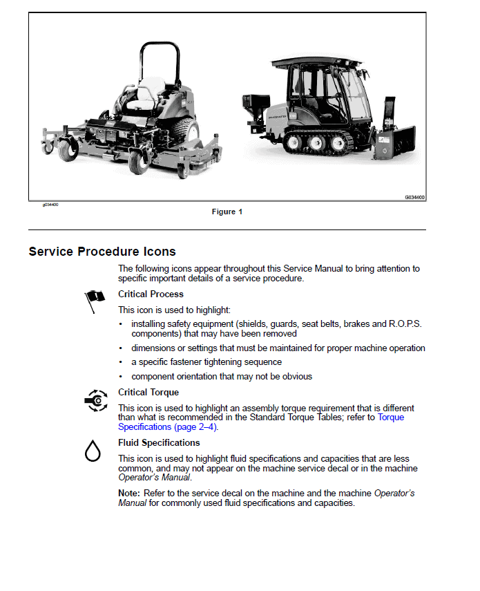
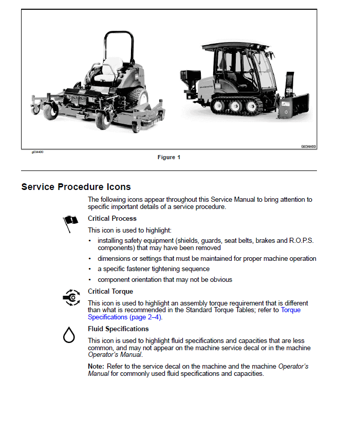
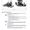
Service Procedure Icons
Chapter 1 : Safety
Safety Instructions
Supervisor’s Responsibilities
Before Operating the Machine
While Operating the Machine
Maintenance and Service
Jacking Instructions
Raising the Front of the Machine
Raising the Rear of the Machine
Safety and Instructional Decals
Chapter 2 : Specifications and Maintenance
Specifications
Decimal and Millimeter Equivalents
U.S. to Metric Conversions
Torque Specifications
Identifying the Fastener
Calculating the Torque Values When Using a Drive-Adapter Wrench
Standard Torque for Dry, Zinc Plated, and Steel Fasteners (Inch Series)
Standard Torque for Dry, Zinc Plated, and Steel Fasteners (Metric Fasteners)
Other Torque Specifications
Conversion Factors
Shop Supplies
Special Tools
Chapter 3 : Diesel Engine
1 Specifications
NO TITLE
General Information
Traction Unit Operator’s Manual
Yanmar Service and Troubleshooting Manuals
Engine Electronic Control Unit (ECU)
Yanmar Engine
Diesel Particulate Filter (DPF)
Service and Repairs
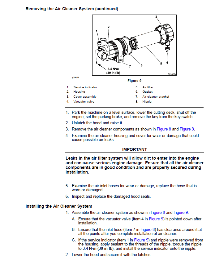
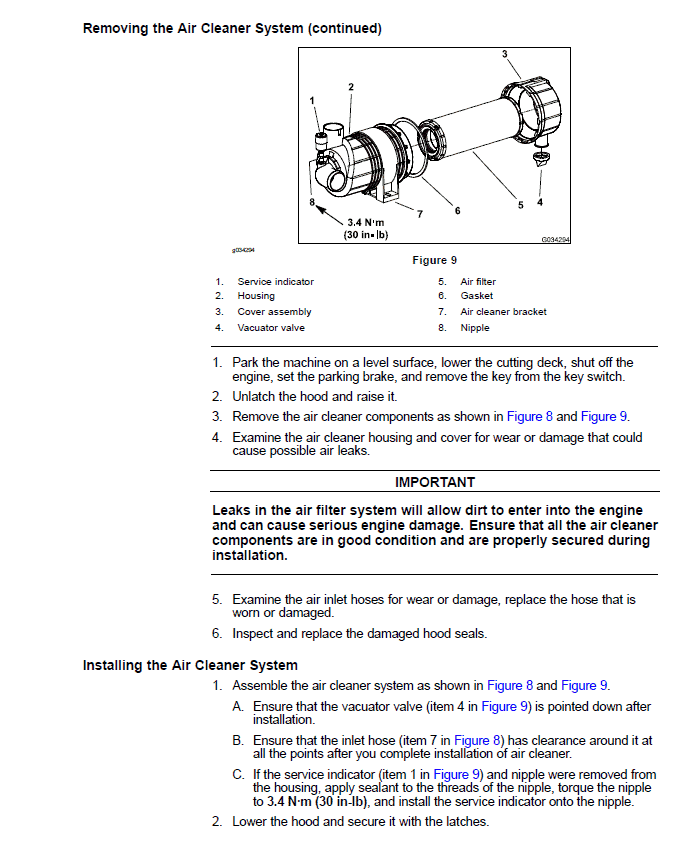
Air Cleaner System
Exhaust System
Radiator
Fuel System
Engine
YANMAR TNV (TIER 4) SERIES Service Repair Manual
YANMAR TNV (TIER 4) SERIES TROUBLESHOOTING MANUAL
Chapter 4 : Hydraulic System
1 Specifications
NO TITLE
General Information
Hydraulic Hoses
Installing the Hydraulic Hose and Tube (O-Ring Face Seal Fitting)
Installing the Hydraulic Fittings (SAE Straight Thread O-Ring Fitting into the Component Port)
Traction Unit Operator’s Manual
Pushing the Traction Unit
Releasing Pressure from the Hydraulic System
Traction Circuit (Closed Loop) Component Failure
Hydraulic Schematics
Traction Circuits
Lift Circuit (Raise)
Lift Circuit (Lower)
PTO Circuit
Special Tools
Hydraulic Pressure Testing Kit
15 GPM Hydraulic Tester Kit (Pressure and Flow)
Hydraulic Test Fitting Kit
O-Ring Kit
High Flow Hydraulic Filter Kit
Hydraulic Hose Kit
Remote Starter Switch
Troubleshooting
General Hydraulic System Problems
Traction Circuit Problems
PTO Circuit Problems
Lift, Lower Circuit Problems
Testing the Hydraulic System
Testing the Traction System Operation
Testing the Charge Relief Valve Pressure (Using Pressure Gauge)
Testing the Transmission Piston Pump Flow (Using Tester with Pressure Gauges and Flow Meter)
Testing the Traction Relief Valve Pressure (Using Tester with Pressure Gauges and Flow Meter)
Testing the Wheel Motor Efficiency (Using Tester with Pressure Gauges and Flow Meter)
Testing the PTO Pressure Valve (Using Pressure Gauge)
Testing the Implement Relief Pressure (Using Pressure Gauge)
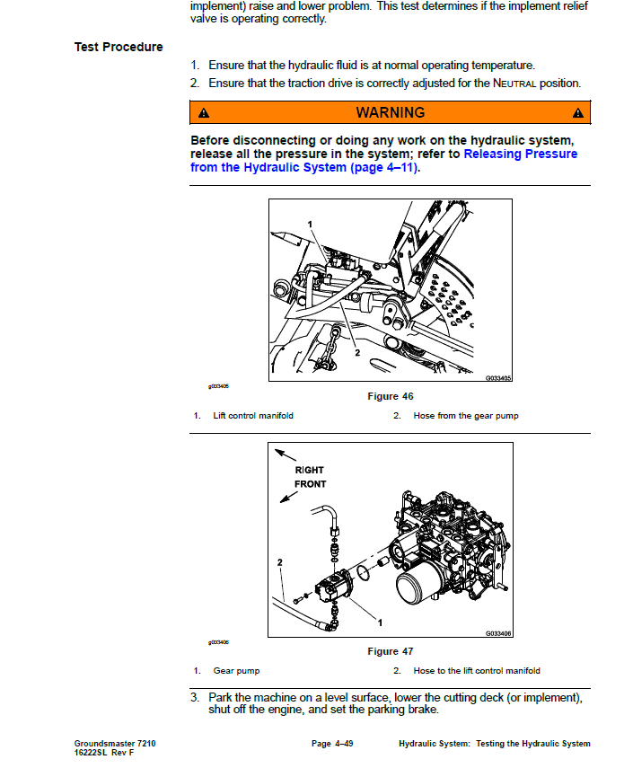
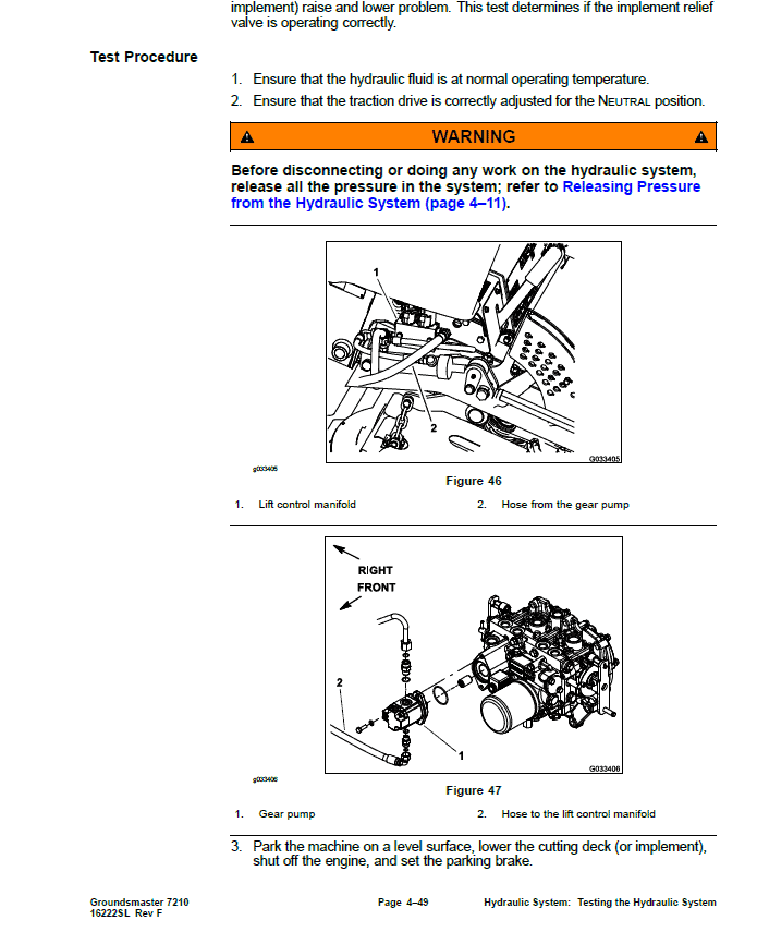
Testing the Gear Pump Flow (Using Tester with Pressure Gauges and Flow Meter)
Testing the Lift Cylinder for Internal Leakage
Service and Repairs
General Precautions for Removing and Installing the Hydraulic System Components
Checking the Hydraulic Lines and Hoses
Priming the Hydraulic Pumps
Flushing the Hydraulic System
Charging the Hydraulic System
Hydraulic Tank
Wheel Motors
Servicing the Wheel Motor
Transmission
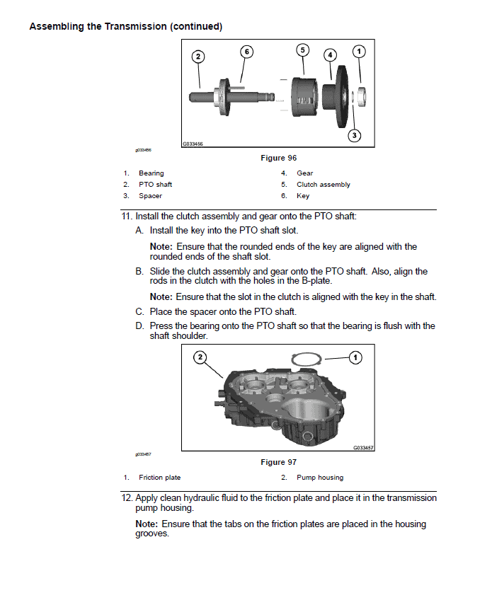
Servicing the Transmission
Gear Pump
Servicing the Gear Pump
Lift Control Manifold
Servicing the Lift Control Manifold
Polar Trac Hydraulic Control Valve
Servicing the Polar Trac Hydraulic Control Valve
Lift Cylinder
Servicing the Lift Cylinder
Polar Trac Lift Cylinder
Servicing the Polar Trac Lift Cylinder
Oil Cooler
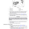
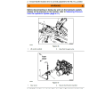
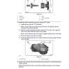
PARKER TORQMOTOR™ SERVICE PROCEDURE (TC, TB, TE, TJ, TF, TG, TH AND TL SERIES)
Chapter 5 : Electrical System
General Information
Standard Control Module
Standard Control Module Logic Chart
Yanmar Engine Electronic Control Unit (ECU)
Yanmar Engine Electrical Components
CAN-bus Communications
Electrical Schematics and Diagrams
Special Tools
Multimeter
Battery Terminal Protector
Battery Hydrometer
Dielectric Gel
InfoCenter Display
Splash Screen
Main Information Screen
Main Menu Screen
Service Screen
Settings Screen
About Screen
Troubleshooting
Starting Problems
General Run and Transport Problems
Cutting Deck Operating Problems
Cutting Deck Lift, Lower Problems
Electrical System Quick Checks
Testing the Battery (Open Circuit Test)
Testing the Charging System
Testing the Glow Plug System
Checking the Operation of the Interlock Switches
Testing the Electrical Components
Key Switch
PTO Switch
Neutral Switches
Seat Switch
Engine Oil Pressure Switch
Parking Brake Sensor
PTO Solenoid Valve Coil
Fusible Link Harness
Diode Assemblies
Resistor Assembly
Glow Relay
Start and EGR Relays
Fuel Pump
Dual Temperature Switch
Fuses
CAN-bus Terminator Resistor
Deck Lift, Lower Switch
Lift Control Manifold Solenoid Valve Coil
Adjustments
Parking Brake Sensor
Service and Repairs
PTO Solenoid Valve Coil
Lift Control Manifold Solenoid Valve Coils
Battery Storage
Battery Care
Servicing the Battery
Chapter 6 : Chassis
1 Specifications
NO TITLE
General Information
Service and Repairs
Rear Wheels
Polar Trac Wheels
Parking Brakes
Servicing the Parking Brake
Parking Brake Assembly
Front Castor Wheels
Servicing the Polar Trac Wheel Hub
PTO Driveshaft
Servicing the PTO Driveshaft Cross and Bearing
Cutting Deck Lift Arms
Rollover Protection System
Operator Seat
Servicing the Operator Seat
Hood
Chapter 7 : Cutting Deck
General Information
Specifications
Cutting Deck Operator’s Manual
Factors That Can Affect Cutting Performance
Service and Repairs
Blade Stopping Time
Cutting Deck
Idler Assembly
Blade Spindle
Servicing the Blade Spindle
Gearbox
Cutting Deck Pull Links
Appendix A: Foldout Drawings
Electrical Drawing Designations
Hydraulic Schematic
Electrical Schematic – Platform (For machine serial number below 403430000)
Electrical Schematic – Platform (For machine serial number above 403430001)
NO TITLE
Electrical Schematic – Engine
Electrical Schematic – Cab (1 of 2)
Electrical Schematic – Cab (2 of 2)
Wire Harness Drawing – Platform (1 of 2) (For machine serial number below 403430000)
Wire Harness Drawing – Platform (2 of 2) (For machine serial number below 403430000)
Wire Harness Drawing – Platform (1 of 2) (For machine serial number above 403430001)
Wire Harness Drawing – Platform (2 of 2) (For machine serial number above 403430001)
Wire Harness Drawing – Engine (1 of 2)
Wire Harness Drawing – Engine (2 of 2)
Wire Harness Drawing – Cab Power
Wire Harness Drawing – Cab Headliner
Wire Harness Diagram – Cab Headliner
Wire Harness Drawing – Cab Power Point Kit
Wire Harness Drawing – Auxiliary Power Model 30382
Wire Harness Drawing – Light Kit Model 30374
Use publication 16222SL with the Groundsmaster 7210 (Tier4) (with Yanmar Engine) model details to select the appropriate documentation. Refer to NOTES: within its stated document and equipment scope.
Reviews
There are no reviews yet.