
THE MANUAL LIBRARY
Toro Groundsmaster 4500-D, 4700-D (Models 30885, 30887, 30893, 30893TE, 30899, 30899TE) Service Repair Manual
$34.00
Documentation Specifications
| Manufacturer | Toro |
| Applicable Model | Groundsmaster 4500-D, 4700-D (Models 30885, 30887, 30893, 30893TE, 30899, 30899TE) |
| Machine Type | Rotary Mowers |
| Documentation | Repair Manual |
| Publication Reference | 19245SL |
| Language | English |
| Format |
Manuals Provided
| Repair Manual | 492 Pages |
For Toro Groundsmaster 4500-D, 4700-D (Models 30885, 30887, 30893, 30893TE, 30899, 30899TE), this reference brings together the listed repair manual material. Start with NOTES and follow the relevant document section for the task.
What’s Covered Inside
Table of Content – Groundsmaster 4500-D, 4700-D (Models 30885, 30887, 30893, 30893TE, 30899, 30899TE)
Title Page
Revision History
Reader Comments
NOTES
Preface
Service Procedure Icons
Chapter 1 : Safety
Safety Instructions
Before Operating the Machine
While Operating the Machine
Maintenance and Service
Jacking Instructions
Safety and Instructional Decals
Chapter 2 : Specifications and Maintenance
Specifications
Overall Dimensions
Engine (Models 30893, 30893TE, 30899 and 30899TE)
Engine (Models 30885 and 30887)
Hydraulic System
Axles, Planetaries and Brakes
Cutting Decks
Torque Specifications
Calculating the Torque Values When Using a Drive-Adapter Wrench
Identifying the Fastener
Standard Torque for Dry, Zinc Plated, and Steel Fasteners (Inch Series)
Standard Torque for Dry, Zinc Plated, and Steel Fasteners (Metric Fasteners)
Other Torque Specifications
Conversion Factors
Shop Supplies
Special Tools
Chapter 3 : Troubleshooting
GEARS – The Systematic Approach to Defining, Diagnosing and Solving Problems
Gather Information
Evaluate Potential Causes
Assess Performance
Repair
Solution Confirmation
General Hydraulic System Problems
Traction Problems
Mow Problems
Steering Problems
Lift Problems
Engine Cooling Fan Problems
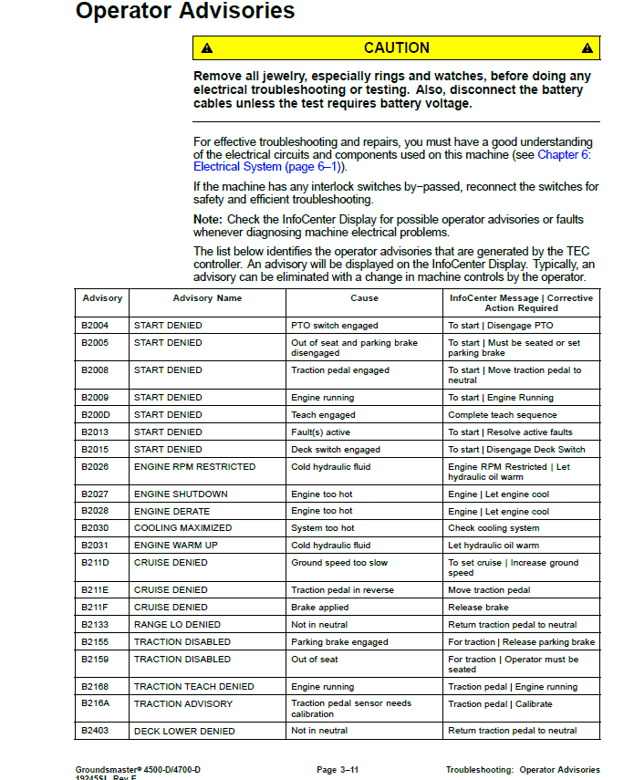
Operator Advisories
Machine Fault Codes
Starting Problems
General Run and Transport Problems
Cutting Deck Operating Problems
Cutting Deck Lift, Lower Problems
Aftercut Appearance
Chapter 4 : Yanmar Diesel Engine
General Information
Operator’s Manual
Yanmar Service and Troubleshooting Manuals
Stopping the Engine
Engine Electronic Control Unit (ECU)
Yanmar Engine: Models 30893, 30893TE, 30899 and 30899TE
Yanmar Engine: Models 30885 and 30887
Diesel Particulate Filter
Service and Repairs
Air Cleaner System
Fuel System
Radiator and Oil Cooler Assembly
Engine
Pump Adaptor Plate
Exhaust System (Models 30885 and 30887)
Yanmar TNV (Tier 4i) Series Service Repair Manual
Yanmar TNV (Tier 4i) Series Troubleshooting Manual
Yanmar TNV (Tier 4) Series Service Repair Manual
Yanmar TNV (Tier 4) Series Troubleshooting Manual
Chapter 5 : Hydraulic System
General Information
Operator’s Manual
Check Hydraulic Fluid
Towing Traction Unit
Relieving Hydraulic System Pressure
Traction Circuit Component Failure
Hydraulic Hoses
Installing Hydraulic Hoses and Tubes (O-Ring Face Seal)
Installing the Hydraulic Fittings (SAE Straight Thread O-Ring Fittings)
Hydraulic Schematic
Hydraulic Flow Diagrams
Traction Circuit: LOW Speed
Traction Circuit: HIGH Speed
Lower Cutting Decks: Groundsmaster 4500-D
Lower Cutting Decks: Groundsmaster 4700-D
Raise Cutting Decks: Groundsmaster 4500-D
Raise Cutting Decks: Groundsmaster 4700-D
Mow Circuit
Cutting Deck Blade Braking
Steering Circuit
Engine Cooling Fan Circuit
Testing
Precautions for Hydraulic Testing
Which Hydraulic Tests Are Necessary?
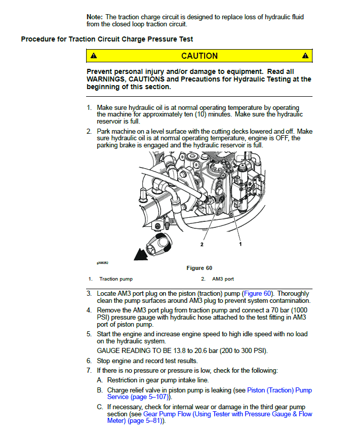
Traction Circuit Charge Pressure (Using Pressure Gauge)
Traction Circuit Relief Pressure (Using Pressure Gauge)
Reverse Traction Circuit Reducing Valve (PR) Pressure (Using Pressure Gauge)
Rear Traction Circuit Relief (RV) Pressure (Using Pressure Gauge)
Piston (Traction) Pump Flow (Using Tester with Pressure Gauge & Flow Meter)
Cutting Deck Circuit Pressure (Using Pressure Gauge)
Cutting Deck Circuit Relief Pressure (Using Tester with Pressure Gauge & Flow Meter)
Deck Motor Case Drain Leakage (Using Tester with Pressure Gauge & Flow Meter)
Steering Circuit Relief Pressure (Using Pressure Gauge)
Steering Cylinder Internal Leakage
Lift, Lower Circuit Relief Pressure (Using Pressure Gauge)
Engine Cooling Fan Circuit (Using Pressure Gauge and Phototac)
Gear Pump Flow (Using Tester with Pressure Gauge & Flow Meter)
Procedure for Gear Pump Flow Test
Adjustments
Adjust Control Manifold Relief Valves
Service and Repairs
General Precautions for Removing and Installing Hydraulic System Components
Check Hydraulic Lines and Hoses
Priming Hydraulic Pumps
Flush Hydraulic System
Filtering Closed−Loop Traction Circuit
Charge Hydraulic System
Gear Pump
Gear Pump Service
Piston (Traction) Pump
Piston (Traction) Pump Service
Rear Traction Control Manifold
Rear Traction Manifold Service
Control Manifold Cartridge Valve Service
Two Speed Shift Manifold
Rear Axle Motor
Front Wheel Motors
Rear Axle and Front Wheel Motor Service
Cutting Deck Motor
Cutting Deck Motor Service
Deck Control Manifold
Deck Control Manifold Service (GM4500-D)
Deck Control Manifold Service (GM4700-D)
Steering Control Valve
Steering Control Valve Service
Steering Cylinder
Steering Cylinder Service
Engine Cooling Fan Motor
Engine Cooling Fan Motor Service
Fan Control Manifold
Fan Control Manifold Service
Lift Control Manifold
Lift Control Manifold Service (GM4500-D)
Lift Control Manifold Service (GM4700-D)
Lift Circuit Junction Manifold
Lift Cylinders: Decks #1, #4 and #5
Lift Cylinders: Decks #2 and #3
Lift Cylinders: Decks #6 and #7 (GM4700-D)
Lift Cylinder Service
Hydraulic Reservoir
Radiator and Oil Cooler Assembly
Danfoss K And L Frame Variable Motors Service Repair Manual
Danfoss Steering Unit Type OSPM Service Repair Manual
Danfoss MP1 Closed Circuit Axial Piston Pumps Service Repair Manual
Chapter 6 : Electrical System
General Information
Operator’s Manual
Electrical Drawings
Toro Electronic Controllers (TEC)
Engine Electronic Control Unit (ECU)
Yanmar Engine Electrical Components
CAN−bus Communications
Electrical Drawings
InfoCenter Display
Adjustments
Traction Pedal Adjustment
Traction Pedal Position Sensor Calibration
Traction Pump Swashplate Angle Sensor Calibration
Electrical System Quick Checks
Battery Test (Open Circuit)
Charging System Test
Check Operation of Interlock Switches
Component Testing
Ignition Switch
Fuses
Fusible Link Harness
PTO Switch
High, Low Speed, Engine Speed Request and Cutting Deck Lift Switches
Headlight Switch
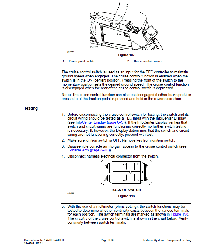
Cruise Control Switch
Seat Switch
Parking Brake Switch
Service Brake Switches
Cutting Deck Position Switches
Relays with Four (4) Terminals
Relays with Five (5) Terminals
Traction Pedal Position Sensor
Swashplate Angle Sensor
Toro Electronic Controllers (TEC)
Hydraulic Solenoid Valve Coils
Piston (Traction) Pump Control Solenoid Coils
Hydraulic Oil Temperature Sender
Traction Pressure Sensor
Fuel Pump (Models 30893, 30893TE, 30899 and 30899TE)
Fuel Pump (Models 30885 and 30887)
CAN−bus Termination Resistor
Diode Assemblies
Resistor Assembly
Capacitor Assembly
Fan Speed Switch (Machines with Two−Post ROPS Extension Operator Fan Kit)
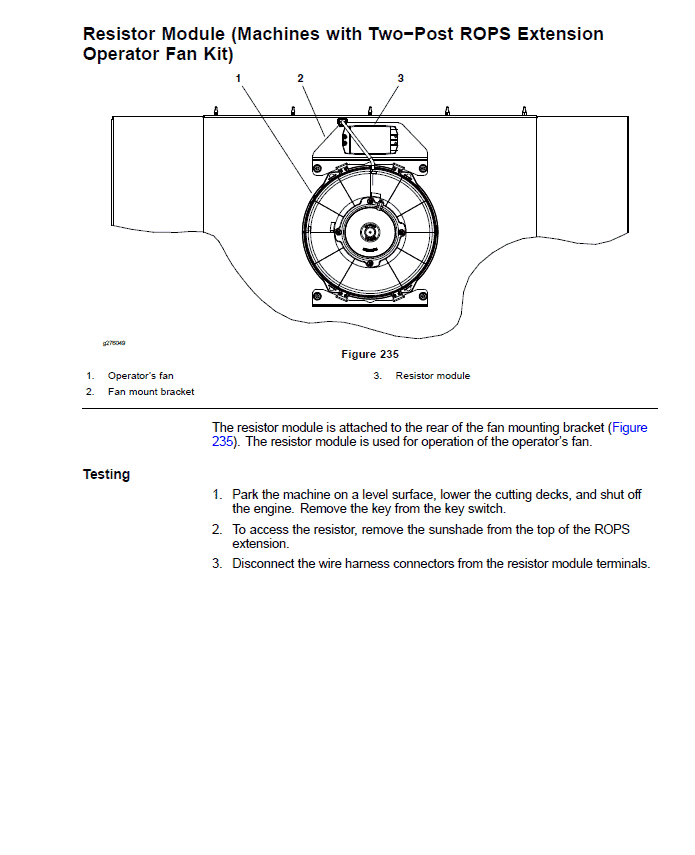
Resistor Module (Machines with Two−Post ROPS Extension Operator Fan Kit)
Service and Repairs
Battery Care
Battery Storage
Battery Service
Chapter 7 : Axles, Planetaries and Brakes
General Information
Operator’s Manual
Adjustments
Planetary Drive Assembly Endplay
Service and Repairs
Brake Assembly
Brake Inspection and Repair
Planetary Drive Assembly
VA02 Series Planetary Drive Service
Rear Axle Assembly
Rear Axle Service
Bevel Gear Case and Axle Case
Differential Shafts
Axle Shafts
Input Shaft, Pinion Gear
Differential Gear
Pinion Gear to Ring Gear Engagement
Gear Pattern Movement Summary
Chapter 8 : Chassis
General Information
Operator’s Manual
Cutting Deck Identification
Service and Repairs
Steering Column
Traction Pedal
Console Arm
Lift Arms for Cutting Decks #1, #4 and #5
Lift Arms for Cutting Decks #2 and #3
Lift Arms for Cutting Decks #6 and #7 (Groundsmaster 4700-D)
Operator Seat
Operator Seat Service
Operator Seat Suspension
Hood
Chapter 9 : Cutting Decks
General Information
Operator’s Manual
Adjustments
Blade Stopping Time
Service and Repairs
Blade Spindle Assembly
Blade Spindle Service
Rear Roller
Rear Roller Service
Front Roller Service
Cutting Deck Carrier Frame
Appendix A: Foldout Drawings
Electrical Drawing Designations
Hydraulic Schematic – Groundsmaster 4500-D
Hydraulic Schematic – Groundsmaster 4700-D
Electric Schematic – Groundsmaster 4500-D, 4700-D (Models 30885 and 30887)
Electric Schematic – Groundsmaster 4500-D, 4700-D (Models 30893, 30893TE, 30899 and 30899TE)
Optional Operator Cab Electrical Schematic – Groundsmaster 4500-D, 4700-D
Main Wire Harness – Groundsmaster 4500-D, 4700-D
Main Wire Harness – Groundsmaster 4500-D, 4700-D
Seat and Console Wire Harness – Groundsmaster 4500-D, 4700-D
Seat and Console Wire Harness – Groundsmaster 4500-D, 4700-D
Power Center Wire Harness – Groundsmaster 4500-D, 4700-D
Power Center Wire Harness – Groundsmaster 4500-D, 4700-D
Deck 6 and 7 Wire Harness – Groundsmaster 4700-D
Deck 6 and 7 Wire Harness – Groundsmaster 4700-D
Engine Wire Harness Drawing – Groundsmaster 4500−D, 4700−D (Models 30885 and 30887) (Serial Numbers Below 408000000)
Engine Wire Harness Drawing – Groundsmaster 4500−D, 4700−D (Models 30885 and 30887) (Serial Numbers Below 408000000)
Engine Wire Harness Drawing – Groundsmaster 4500−D, 4700−D (Models 30885 and 30887) (Serial Numbers Above 408000000)
Engine Wire Harness Drawing – Groundsmaster 4500−D, 4700−D (Models 30885 and 30887) (Serial Numbers Above 408000000)
Engine DPF Wire Harness Drawing – Groundsmaster 4500−D, 4700−D (Models 30885 and 30887) (Serial Numbers Above 408000000)
NO TITLE
Engine Wire Harness Drawing – Groundsmaster 4500−D, 4700−D (Models 30893, 30893TE, 30899 and 30899TE)
Engine Wire Harness Drawing – Groundsmaster 4500−D, 4700−D (Models 30893, 30893TE, 30899 and 30899TE)
Wire Harness Diagram – Two−Post ROPS Extension
Wire Harness Diagram – Two−Post ROPS Extension
Use publication 19245SL with the Groundsmaster 4500-D, 4700-D (Models 30885, 30887, 30893, 30893TE, 30899, 30899TE) model details to select the appropriate documentation. Refer to NOTES within its stated document and equipment scope.
Reviews
There are no reviews yet.