
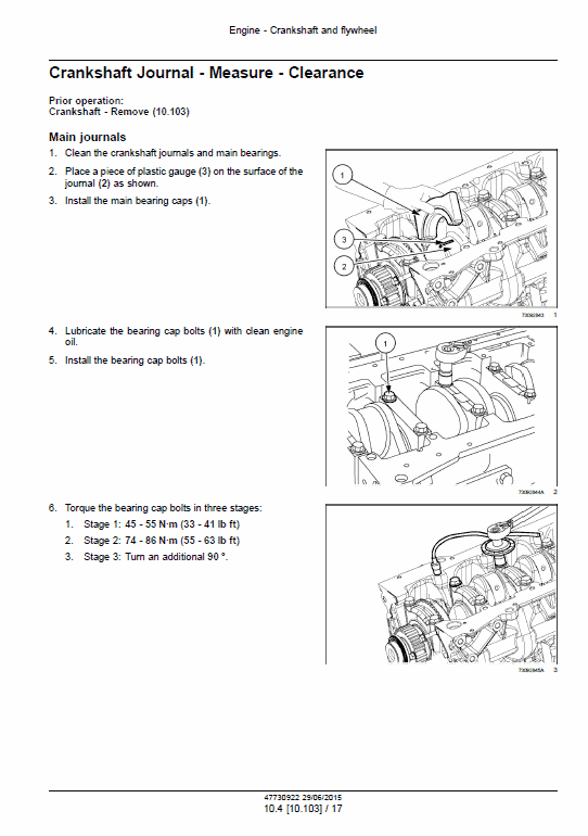
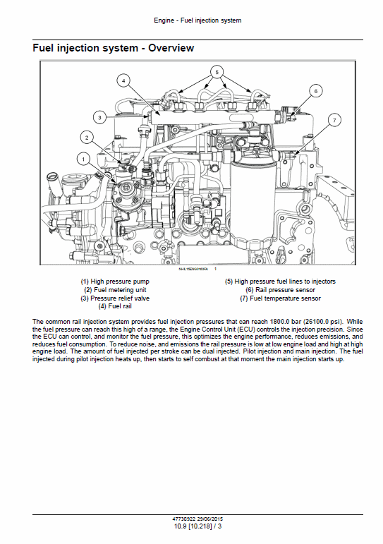
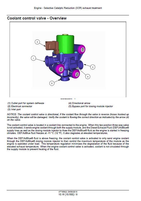
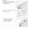
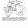
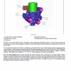
Crankshaft pages illustrate measuring bearing clearance, the small working gap between the shaft and its bearing. A common-rail diagram identifies the fuel pump, shared pressure rail, injectors and sensors. Exhaust-treatment material explains components used to control emissions, including the coolant valve associated with the exhaust-fluid system. This is engine documentation rather than a complete machine service manual.
Systems & Components Covered
- Internal engine assemblies: Cylinder head, crankcase, crankshaft, pistons, connecting rods and valve-drive components.
- Fuel and air supply: Filters, injection equipment, turbocharger, intake and exhaust passages.
- Lubrication and cooling: Oil pump, coolant system, oil cooler, fan and associated lines.
- Exhaust-treatment equipment: Selective catalytic reduction and exhaust-gas recirculation, the systems used to reduce emissions.
- Engine-control electrics: Sensors, injection controls and monitoring of oil, cooling and air systems.
- Starting and charging: Starter, cold-start assistance, alternator and emissions-system electrical components.
The Digital Workshop Advantage
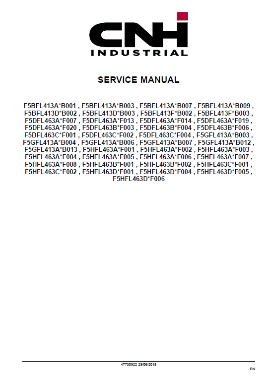
The applicability pages and the code at the top of a procedure help identify which engine arrangement is being described. Component keys explain the fuel-system drawings, while measurement illustrations show where clearances are taken. These references are useful when similar-looking parts appear across different F5 variants.


Reviews
There are no reviews yet.