


Overview
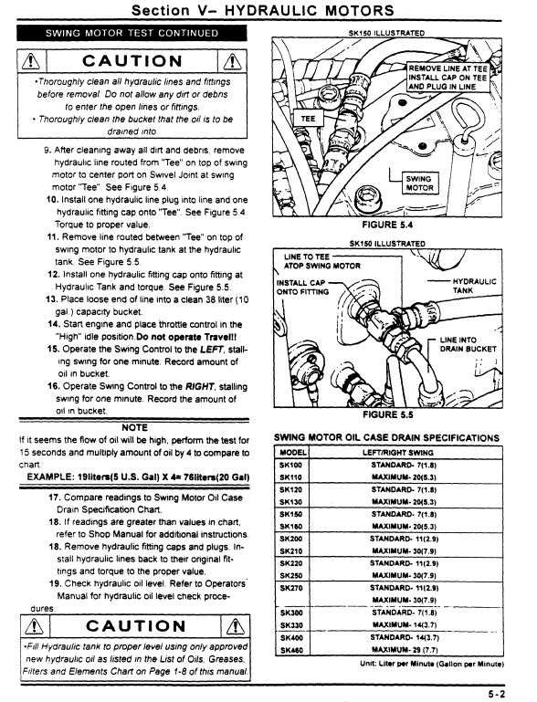
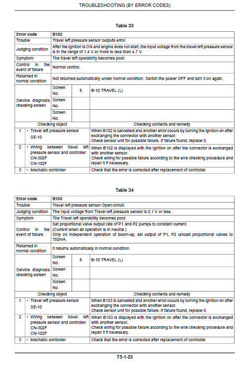
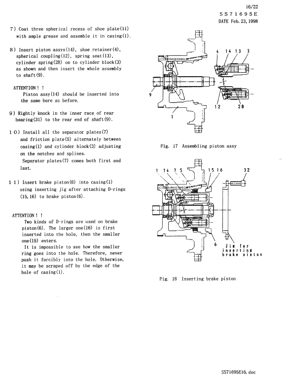
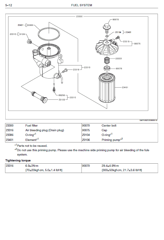
The Kubota U10, U20, U30, U45 excavator repair service manual provides a technical reference for the covered equipment. Its purpose is to help locate information relevant to inspection, troubleshooting, servicing and repair, as applicable to the supplied publication.
The documented contents outline identifies kubota excavator model u10, u20, u30, u45, i general, ii machine body and mechanism section . . . . . . . . . . . . . . . . . . . . . . . . . . . . . .ii-m-1. The table below lists selected source-supported subjects; consult the publication for exact service procedures and specifications.
Table of Contents
Kubota U10, U20, U30, U45 Manual
Main sections and selected subjects identified in the source documentation:
- Kubota Excavator Model U10, U20, U30, U45
- I General
- II Machine body
- Mechanism Section . . . . . . . . . . . . . . . . . . . . . . . . . . . . . .II-M-1
- Service Section . . . . . . . . . . . . . . . . . . . . . . . . . . . . . . . . .II-S-1
- III Engine
- Mechanism Section . . . . . . . . . . . . . . . . . . . . . . . . . . . . . .III-M-1
- Service Section . . . . . . . . . . . . . . . . . . . . . . . . . . . . . . . . .III-S-1
- IV Hydraulic System
- Mechanism Section . . . . . . . . . . . . . . . . . . . . . . . . . . . . . .IV-M-1
- Service Section . . . . . . . . . . . . . . . . . . . . . . . . . . . . . . . . .IV-S-1
- ELECTRICAL SYSTEM
- Mechanism Section . . . . . . . . . . . . . . . . . . . . . . . . . . . . . . . . . . . . V-M-1
- Service Section. . . . . . . . . . . . . . . . . . . . . . . . . . . . . . . . . . . . . . . . V-S-1
- U10, U20, U30, U45
- IMPORTANT INSPECTION ITEMS AFTER REASSEMBLING
- a Operate the Kubota U10, U20, U30, U45 Excavator and check for Unusual Noise and Vibrations.
- b Make Sure the Safety decals and Wire harness Clamps are in their Specified Positions.
- 1) Park the machine on a level ground.
- 3) Keep the machine front as shown as following posture.
- Harness check Mode Kubota U10, U20, U30, U45
- By selecting Other menu and Circuit check Engine stop, the present conditions of the harness connector can be checked (See fig. below.).
- While in harness check mode, the following items can be checked. Items in parentheses are error criteria.
- Lever lock switch (OFF When lever is down).
- Fuel sensor (Reading of 2 V or more, or 0.2 V or less.).
- Water temperature (Water temperature of 140 C or more, or -30 C or lower.).
- Oil switch (OFF When engine stops and Key is ON).
- Charge circuit (OFF).
Using the Technical Reference
Use the identified sections to locate relevant information, and follow any model-specific instructions, limits and precautions in the original documentation.


Reviews
There are no reviews yet.