
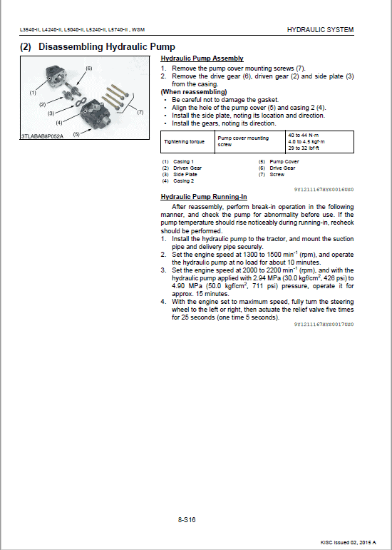
For Kubota L3540-II, L4240-II, L5040-II, L5240-II, L5740-II Tractor, this reference brings together the listed repair manual material. Start with Information and follow the relevant document section for the task.
What’s Covered Inside
Kubota Tractor Model L3540-II, L4240-II, L5040-II, L5240-II, L5740-II
Table of Content of the Workshop Service Manual
Information
General
Engine
Clutch
Transmission
Rear Axle
Brakes
Front Axle
Steering
Hydraulic System
Electrical System
Cabin
This Workshop Manual tells the servicing personnel about the mechanism, servicing and maintenance of the L3540-II, L4240-II, L5040-II, L5240-II, L5740-II. It contains 4 parts: “Information”, “General”, “Mechanism” and “Servicing”.
– Information
This section contains information below.
Safety First
Safety Decal
Specification
Dimension
– General
This section contains information below.
Engine Identification
Model Identification
General Precautions
Maintenance Check List
Check and Maintenance
Special Tools
– Mechanism
This section contains information on the structure and the function of the unit. Before you continue with the subsequent sections, make sure that you read this section.
Refer to the latest version of Workshop Manual (Code No. 9Y021-01870 / 9Y021-18200) for the diesel engine / tractor mechanism that this workshop manual does not include.
– Servicing
This section contains information below.
Troubleshooting
Servicing Specifications
Tightening Torques
Checking, Disassembling and Servicing
Manual Extract – Oil Flow
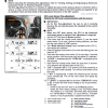
Oil is sucked into the charge pump through the a-port and pass through the HST filter. Then oil passes through the b-port and fed into the HST. Then oil is supplied to the main circuit of the HST as charge oil by means of the charge relief valve.
Oil from the b-port passes through the c-port and is supplied to the Hi-Lo solenoid valve. When the Hi-Lo solenoid valve is switched, the Hi-Lo spool is switched by the oil pressure of the main circuit of the HST. When the Hi-Lo solenoid valve is switched “ON”, the Hi-Lo spool is activated by the oil pressure of the main circuit of the HST.
When the Hi-Lo solenoid valve is switched “OFF”, the Hi-Lo spool is activated by the charge pressure. When the Hi-Lo spool is switched “ON”, oil on the high-pressure side (forward or backward) passes through the spool (pressure selector) and flows to the piston H (9).
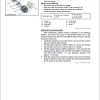
Oil from the hydraulic pump is fed to the c-port of the regulator valve. The regulator valve sets the pressure of the PTO valve and proportional valve.
Oil from the regulator valve is guided to the servo piston by the motion of the proportional valve. The proportional valve is controlled by the operation of the HST pedal.
Oil from the regulator valve is supplied to the PTO valve and power steering controller.
Use publication 9Y111-11670 with the L3540-II, L4240-II, L5040-II, L5240-II, L5740-II model details to select the appropriate documentation. Refer to Information within its stated document and equipment scope.


Reviews
There are no reviews yet.