
Overview
The Komatsu WB140-2N and WB150-2N backhoe loader repair service manual provides a technical reference for the covered equipment. Its purpose is to help locate information relevant to inspection, troubleshooting, servicing and repair, as applicable to the supplied publication.
The supplied contents outline identifies Manuals, 01 GENERAL . . . . . . . . . . . . . . . . . . . . . . . . . . . . . . . . . . . . . . . . . . . . . . . . . . . . . . . . . . . . . 01-1, 10 STRUCTURE, FUNCTION AND MAINTENANCE STANDARD . . . . . . . . . . . . . . . . . . . . 10-1 and 20 TESTING, ADJUSTING AND TROUBLESHOOTING . . . . . . . . . . . . . . . . . . . . . . . . . . . . 20-1. The table below follows the provided section names and selected topics; consult the manual for the exact procedures and specifications.
Important Information: Confirm the applicable serial-number or production range in the supplied documentation before selecting a procedure.
Table of Contents
Komatsu WB140-2N and WB150-2N Manual
Main sections and selected subjects identified in the source documentation:
- Manuals: Shop Manual
- 01 GENERAL . . . . . . . . . . . . . . . . . . . . . . . . . . . . . . . . . . . . . . . . . . . . . . . . . . . . . . . . . . . . . 01-1
- 10 STRUCTURE, FUNCTION AND MAINTENANCE STANDARD . . . . . . . . . . . . . . . . . . . . 10-1
- 20 TESTING, ADJUSTING AND TROUBLESHOOTING . . . . . . . . . . . . . . . . . . . . . . . . . . . . 20-1
- 30 DISASSEMBLY AND ASSEMBLY. . . . . . . . . . . . . . . . . . . . . . . . . . . . . . . . . . . . . . . . . . . 30-1
- 90 OTHER. . . . . . . . . . . . . . . . . . . . . . . . . . . . . . . . . . . . . . . . . . . . . . . . . . . . . . . . . . . . . . . . 90-1
- GENERAL
- STRUCTURE, FUNCTION AND MAINTENANCE STANDARD
- TESTING, ADJUSTING AND TROUBLESHOOTING
- DISASSEMBLY AND ASSEMBLY
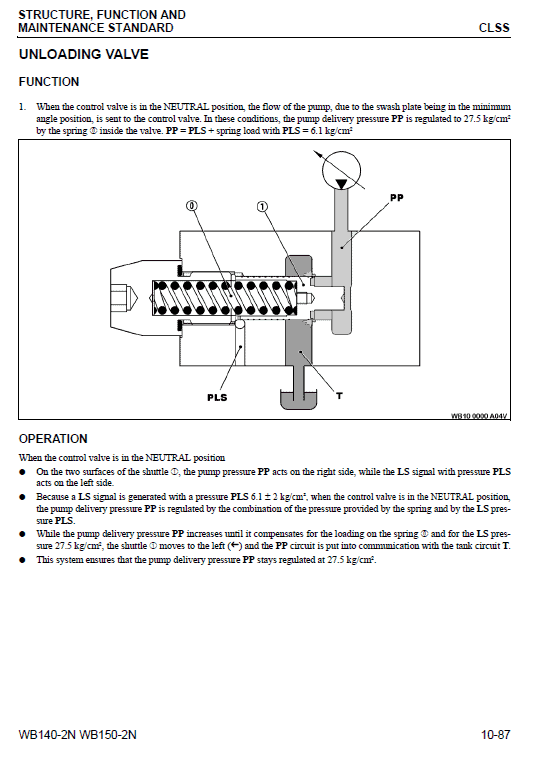
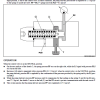
- FLOW VALVE TESTING
- Disconnect the hose a from the load sensing line. Install the tee b and reconnect the hose.
- Connect a pressure port and gauge E1 to the tee b.
- Connect a second gauge E1 to the rear control valve pressure port c.
- Start the engine and at low idle without any machine movement, check the pressure on both gauges.
- P pressure at control valve gauge: 30 3 kg/cm Normal pressure PLS: 6 2 kg/cm
- This value is due to the influence of the counter pressure present in the steering circuit.
- If any variations are found, they do not represent a problem provided that the difference of 21 1 kg/cm between the two readings is respected.
- If the difference between the readings is higher than 24 1 kg/cm, stop the engine and release the residual pressures.
- Thoroughly clean the valve d and reinstall it.
- Valve = 20 N.M
- If, after cleaning the valve d, the value still does not fall within the tolerance limits of 24 1 kg/cm, install a new valve.
Serial-Number Applicability
The covered production ranges or serial groups may affect the applicable procedures. Check the identification details on the machine against the source documentation.


Reviews
There are no reviews yet.