

Overview
The Komatsu PC300-7, PC300LC-7, PC350-7, PC350LC-7 excavator repair service manual provides a technical reference for the covered equipment. Its purpose is to help locate information relevant to inspection, troubleshooting, servicing and repair, as applicable to the supplied publication.
The documented contents outline identifies pc300lc-7: 40001 and up, pc350lc-7: 20001 and up, manuals: shop manual and 01 general . . . . . . . . . . . . . . . . . . . . . . . . . . . . . . . . . . . . . . . . . . . . . . . . . . . . . . . . . . . . . 01-1. The table below lists selected source-supported subjects; consult the publication for exact service procedures and specifications.
Important Information: Confirm the applicable serial-number or production range in the supplied documentation before selecting a procedure.
Table of Contents
Komatsu PC300-7, PC300LC-7, PC350-7, PC350LC-7 Manual
Main sections and selected subjects identified in the source documentation:
- PC300LC-7: 40001 and up
- PC350LC-7: 20001 and up
- Manuals: Shop Manual
- 01 GENERAL . . . . . . . . . . . . . . . . . . . . . . . . . . . . . . . . . . . . . . . . . . . . . . . . . . . . . . . . . . . . . 01-1
- 10 STRUCTURE AND FUNCTION. . . . . . . . . . . . . . . . . . . . . . . . . . . . . . . . . . . . . . . . . . . . . 10-1
- 20 TESTING, ADJUSTING AND TROUBLESHOOTING . . . . . . . . . . . . . . . . . . . . . . . . . . . . 20-1
- 30 DISASSEMBLY AND ASSEMBLY. . . . . . . . . . . . . . . . . . . . . . . . . . . . . . . . . . . . . . . . . . . 30-1
- 90 OTHER. . . . . . . . . . . . . . . . . . . . . . . . . . . . . . . . . . . . . . . . . . . . . . . . . . . . . . . . . . . . . . . . 90-1
- Composition of shop manual
- ease of understanding, the manual is divided into the following sections.
- FOREWORD
- This section explains the safety and basic information.
- GENERAL
- This section explains the specifications of the machine for the Excavator.
- STRUCTURE AND FUNCTION, MAINTENANCE STANDARD
- This section explains the structure, function, and maintenance standard values of each component.
- TESTING AND ADJUSTING
- Standard value table
- Troubleshooting
- DISASSEMBLY AND ASSEMBLY For Excavator
- OTHERS (chassis volume)/Repair and replacement of parts (engine volume)
- Chassis volume
- This section gives hydraulic circuit diagrams and electrical circuit diagrams.
- Engine volume
- This section explains the method of reproducing, repairing, and replacing parts.
- REMOVAL AND INSTALLATION OF MONITOR ASSEMBLY REMOVAL
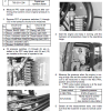
- First, disconnect the cable from the negative () terminal of the battery.
- Remove cover (1) and then disconnect the wiring connector P15 for air conditioner sunlight sensor (2).
- Lift the cover up to remove it.
- Remove the three mounting screws and remove monitor assembly (3).
Serial-Number Applicability
The covered production ranges or serial groups may affect the applicable procedures. Check the identification details on the machine against the source documentation.


Reviews
There are no reviews yet.