

Overview
The Komatsu HM300-1L dump truck repair service manual provides a technical reference for the covered equipment. Its purpose is to help locate information relevant to inspection, troubleshooting, servicing and repair, as applicable to the supplied publication.
The supplied contents outline identifies Manuals, 01 GENERAL . . . . . . . . . . . . . . . . . . . . . . . . . . . . . . . . . . . . . . . . . . . . . . . . . . . . . . . . . . . . . 01-1, 10 STRUCTURE AND FUNCTION. . . . . . . . . . . . . . . . . . . . . . . . . . . . . . . . . . . . . . . . . . . . . 10-1 and 20 TESTING, ADJUSTING AND TROUBLESHOOTING . . . . . . . . . . . . . . . . . . . . . . . . . . . . 20-1. The table below follows the provided section names and selected topics; consult the manual for the exact procedures and specifications.
Important Information: Confirm the applicable serial-number or production range in the supplied documentation before selecting a procedure.
Table of Contents
Komatsu HM300-1L Manual
Main sections and selected subjects identified in the source documentation:
- Manuals: Shop Manual and Operation and Maintenance Manual
- 01 GENERAL . . . . . . . . . . . . . . . . . . . . . . . . . . . . . . . . . . . . . . . . . . . . . . . . . . . . . . . . . . . . . 01-1
- 10 STRUCTURE AND FUNCTION. . . . . . . . . . . . . . . . . . . . . . . . . . . . . . . . . . . . . . . . . . . . . 10-1
- 20 TESTING, ADJUSTING AND TROUBLESHOOTING . . . . . . . . . . . . . . . . . . . . . . . . . . . . 20-1
- 30 DISASSEMBLY AND ASSEMBLY. . . . . . . . . . . . . . . . . . . . . . . . . . . . . . . . . . . . . . . . . . . 30-1
- 90 DIAGRAMS AND SCHEMATICS. . . . . . . . . . . . . . . . . . . . . . . . . . . . . . . . . . . . . . . . . . . . 90-1
- GENERAL
- STRUCTURE, FUNCTION AND MAINTENANCE STANDARD
- TESTING, ADJUSTING AND TROUBLESHOOTING KOMATSU Dump Truck HM300-1L
- DISASSEMBLY AND ASSEMBLY
- TRUCK BODY ASSEMBLY REMOVAL
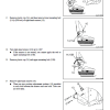
- Remove both hoist cylinder rod pins (1).
- Sling the bottom of the hoist cylinder temporarily.
- Loosening lever block B, lower the crane to place the bottom of the hoist cylinder on the tire.
- A. Place block C between the bottom of the hoist cylinder and tire.
- B. Install lever block B between the vehicle body and hoist cylinder and tense it to prevent the hoist cylinder from falling down.
- Sling the body temporarily.
- Disconnect body potentiometer linkage (2) from the body.
- Remove body hinge pins (3) on both sides.
- Lift off body assembly (4).
- Body assembly: 4450 kg (9,811 lbs)
Serial-Number Applicability
The covered production ranges or serial groups may affect the applicable procedures. Check the identification details on the machine against the source documentation.


Reviews
There are no reviews yet.