
Overview
The Komatsu CK20-1 skid steer loader repair service manual provides a technical reference for the covered equipment. Its purpose is to help locate information relevant to inspection, troubleshooting, servicing and repair, as applicable to the supplied publication.
The supplied contents outline identifies Manuals, STRUCTURE AND FUNCTION, TESTING AND ADJUSTING and REMOVAL AND INSTALLATION. The table below follows the provided section names and selected topics; consult the manual for the exact procedures and specifications.
Important Information: Confirm the applicable serial-number or production range in the supplied documentation before selecting a procedure.
Table of Contents
Komatsu CK20-1 Manual
Main sections and selected subjects identified in the source documentation:
- Manuals: Shop Manual
- STRUCTURE AND FUNCTION
- TESTING AND ADJUSTING
- REMOVAL AND INSTALLATION
- MAINTENANCE STANDARD
- OTHER
- This CK20-1 shop manual is an aid to improve the quality of repairs by giving the operator an accurate
- understanding of the product and by showing him the correct way to perform repairs and make judgements. Make sure
- you understand the contents of this manual and use it to full effect at every opportunity.
- workshop.
- following sections.
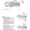
- This section explains the structure and function of each component. It serves not only to give an understanding
- of the structure, but also serves as reference material for troubleshooting.
- TESTING AND ADJUSTMENTS
- Troubleshooting charts correlating Problems to Causes are also included in this section.
- STANDARD MAINTENANCE
- This section gives the judgement standards when inspecting disassembled parts
- ADJUSTMENT OF THE PPC VALVE CLEARANCES
- The clearance of the PPC valve (hand and foot) levers is adjust as follows.
- k Lower the working equipment to the ground and stop the engine.
- Turn the ignition key to the I position and move the control levers in all directions in order to release all pressure in the hydraulic circuits.
- Return the ignition key to the O (OFF) position and remove it.
- Slowly loosen the oil-tank fill cap to eliminate residual pressure.
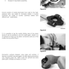
- Remove boot (1).
- Loosen the nut (2) that retains the disc (3).
- Tighten the disc (3) until it makes light contact with the 4 push-rods (4).
- a During this adjustment, take care not to activate any of the push-rods (4) individually.
- Secure this position by tightening the retaining nut (2) to the specific torque. 3Retaining nut: 11315 Nm
Serial-Number Applicability
The covered production ranges or serial groups may affect the applicable procedures. Check the identification details on the machine against the source documentation.


Reviews
There are no reviews yet.