
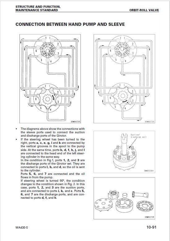
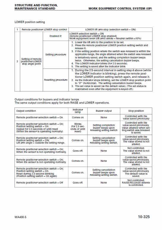
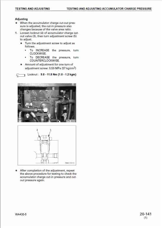

For Komatsu WA430-5 Wheel Loader, this reference brings together the listed repair manual material. Start with 01 GENERAL and follow the relevant document section for the task.
What’s Covered Inside
01 GENERAL …………………………………………………………………………….. 01-1
10 STRUCTURE, FUNCTION AND MAINTENANCE STANDARD …… 10-1
20 TESTING AND ADJUSTING ……………………………………………………. 20-1
30 DISASSEMBLY AND ASSEMBLY ……………………………………………..30-1
90 OTHERS ……………………………………………………………………………….. 90-1
Outline of the DRIVE SHAFT (PROPELLER SHAFT)
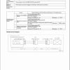
The power from the transmission output shaft passes through center drive shaft (3), front drive shaft (1), and rear drive shaft (4), and is transmitted to the front axle and rear axle.
When the body is articulated, or when the machine is traveling and there is shock from the ground surface, or when there is shock during operations, the position of the transmission and the front and rear axles changes. The transmission is designed so that even if the position of the components changes as a result of such shock, power can be transmitted without damage to any parts. With this design, the drive shafts have universal joints and flange bearings that enable them to handle any changes in the angle and length.
Use publication SEBM028006 and VEBM320100 with the WA430-5 model details to select the appropriate documentation. Refer to 01 GENERAL within its stated document and equipment scope.


Reviews
There are no reviews yet.