


For Komatsu PC80MR-3 Excavator, this reference brings together the listed repair manual material. Start with 10. STRUCTURE AND FUNCTION and follow the relevant document section for the task.
What’s Covered Inside
10. STRUCTURE AND FUNCTION…………………………………………………………………….. 10-1
20. TESTING AND ADJUSTING ………………………………………………………………………… 20-1
30. DISASSEMBLY AND ASSEMBLY ……………………………………………………………….. 30-1
90. OTHER………………………………………………………………………………………………………. 90-1
This Komatsu PC80MR-3 service manual has been prepared as an aid to improve the quality of repairs by giving the operator an accurate understanding of the product and by showing him the correct way to perform repairs and make judgements. Make sure you understand the contents of this manual and use it to full effect at every opportunity.
STRUCTURE AND FUNCTION
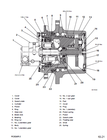
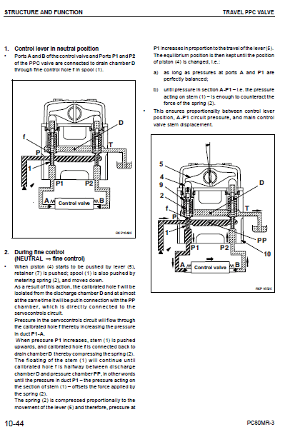
This section explains the structure and function of each component. It serves not only to give an understanding of the structure, but also serves as reference material for troubleshooting.
TESTING AND ADJUSTMENTS
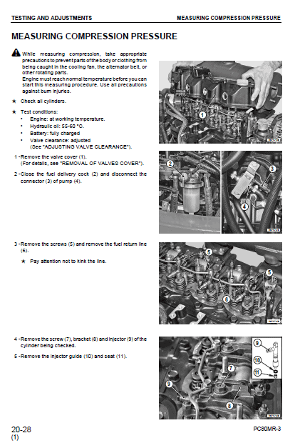
This sections explains checks to be made before and after performing repairs, as well as adjustments to be made at completion of the checks and repairs.
Troubleshooting charts correlating Problems to Causes are also included in this section.
REMOVAL AND INSTALLATION FOR Komatsu PC80MR-3
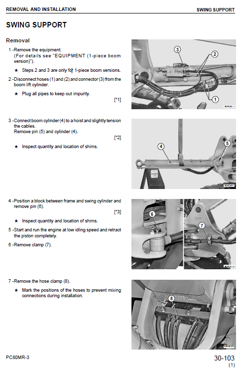
This section explains the order to be followed when removing, installing, disassembling or assembling each component, as well as precautions to be taken for these operations.
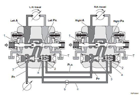
When traveling in a straight line
Function
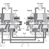
To compensate for any difference in the oil flow in the left and right travel circuits when traveling in a straight line, the junction circuit opens when the left and right travel spools are operated.
In this way, the flow of oil to the left and right travel motors is almost the same when traveling in a straight line, so there is no travel deviation.
When steering the machine, the difference in the load pressure returns the reducing valve of the travel valve on the inside of the turn, so the junction circuit is closed and the machine can be steered.
Operation
When left and right travel spools (1) are operated, the pump discharge flows from pump circuit PP and circuit PA to actuator circuit A.
When traveling in a straight line, to make actuator circuit PA equal, left and right reducing valves (2) are pushed to the right (o) by the same amount, and notch a and the travel junction circuit are opened.
In this way, the left and right travel actuator circuits are interconnected by the travel junction circuit, so if any difference occurs in the flow of oil to the left and right travel motors, the difference is compensated to prevent any deviation in travel.
Use publication SEBM016404 with the PC80MR-3 model details to select the appropriate documentation. Refer to 10. STRUCTURE AND FUNCTION within its stated document and equipment scope.


Reviews
There are no reviews yet.