
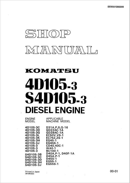
For Komatsu 4D105-3, S4D105-3 Diesel Engine, this reference brings together the listed engine manual material. Start with 01 GENERAL and follow the relevant document section for the task.
What’s Covered Inside
01 GENERAL ……………………………………………….. 01-001
11 STRUCTURE AND FUNCTION …………………….. 11-001
12 TESTING AND ADJUSTING ……………………….. 12-001
13 DISASSEMBLY AND ASSEMBLY ………………… 13-001
14 MAINTENANCE STANDARD ………………………. 14-001
15 REPAIR AND REPLACEMENT ……………………… 1s-001
GENERAL DESCRIPTION
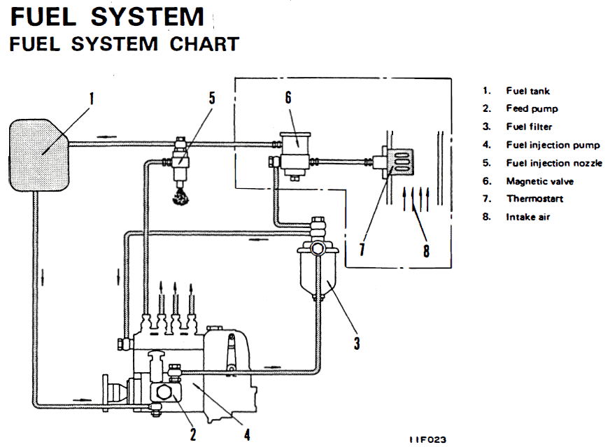
1. Structure of fuel system
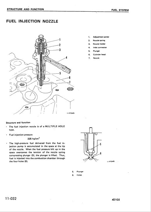
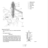
The fuel system consists mainly of the fuel tank, feed pump, fuel filter, fuel injection pump, fuel injection nozzles and governor (built as one unit with the fuel injection pump).
In addition 40105, S4O105 supply fuel to thermostart for easy starting.
2. Circulation of fuel
1) Fuel is delivered from the fuel tank to the injection pump through the fuel filter by the feed pump driven by ·the fuel injection pump cam. During the course from the tank to the injection pump, the fuel is cleaned of rough dirt through the gauge filter at the inlet to the feed pump. Then, complete dust removal and water separation from the oil are accomplished through the filter.
2) Fuel entering the injection pump is pressurized by the pump plunger to that required for injection and injected into each cylinder through the injection nozzle in the quantity required, meeting the injection timing for the cylinder.
3) The excess fuel at the nozzles or in the thermostart tank ( 40105, S4O105) in the fuel circuit flows back to the fuel tank through the spill pipes.
Use publication SEBE61300300 with the 4D105-3, S4D105-3 model details to select the appropriate documentation. Refer to 01 GENERAL within its stated document and equipment scope.


Reviews
There are no reviews yet.