
For Komatsu HM400-3 Dump Truck, this reference brings together the listed repair manual material. Start with 01 Specification and follow the relevant document section for the task.
What’s Covered Inside
Service Manual: 2231 pages
Operation and Maintenance Manual: 415 pages
Field Assembly: 27 pages
Manuals: Service Manual, Operation and Maintenance Manual and Field Assembly
00 Index and foreword
01 Specification
10 Structure, function and maintenance standard
20 Standard value table
30 Testing and adjusting
40 Troubleshooting
50 Disassembly and assembly
90 Diagrams and drawings
Composition of Service manual for KOMATSU Dump Truck HM400-3
00. Index and foreword
This section includes the index, foreword, safety and basic information.
01. Specification
This section explains the specifications of the machine.
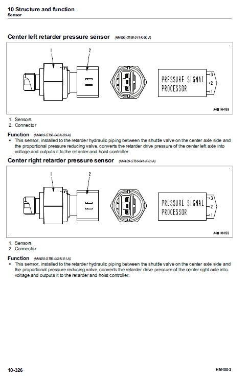
10. Structure and function
This section explains the structure and function of the machine. The section of “Structure and function”
serves not only to give an understanding for the structure of each component, but also serves as
reference material for troubleshooting.
20. Standard value table
The standard values for a new machine and trouble shooting are indicated. This standard value table is
used for testing and adjusting, and determining a failure at troubleshooting.
30. Testing and adjusting
This section describes the measuring tools and how to measure, and how to adjust various parts. As for
the standard value and failure criterion, see the standard value table.
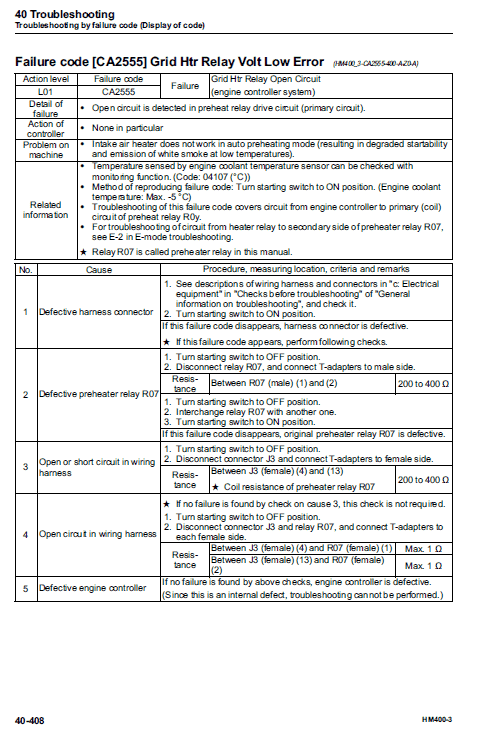
40. Troubleshooting
This section describes the troubleshooting in a suspected area when a failure occurs and the remedy for
the failure. Troubleshooting is described by each failure mode.
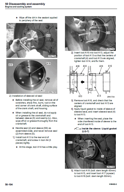
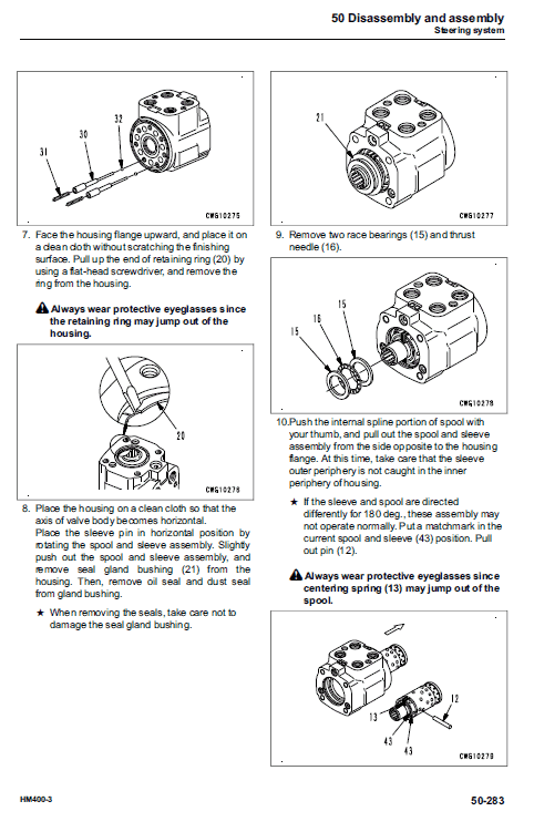
50. Disassembly and assembly KOMATSU Dump Truck HM400-3
This section explains the procedures for removing, installing, disassembling, and assembling each part or
component and the special tools for the works as well as precautions for doing them safely. In addition,
tightening torque, and quantity and weight of coating material, oil, grease, and coolant required for the
works are also explained.
60. Maintenance standard
This section describes the maintenance standard values for each component. This section gives the
criterion values for each component and required remedy at disassembly or maintenance.
80. Appendix
The structure and function, testing and adjusting, and troubleshooting for all of the other components or
equipment which can not be separately classified are explained together in the appendix.
90. Diagrams and drawings
This section gives hydraulic circuit diagrams and electrical circuit diagrams.
Operation and Maintenance Manual: 415 pages
Field Assembly: 27 pages
Manuals: Service Manual, Operation and Maintenance Manual and Field Assembly
00 Index and foreword
01 Specification
10 Structure, function and maintenance standard
20 Standard value table
30 Testing and adjusting
40 Troubleshooting
50 Disassembly and assembly
90 Diagrams and drawings
Composition of Service manual for KOMATSU Dump Truck HM400-3
00. Index and foreword
This section includes the index, foreword, safety and basic information.
01. Specification
This section explains the specifications of the machine.
10. Structure and function
This section explains the structure and function of the machine. The section of “Structure and function”
serves not only to give an understanding for the structure of each component, but also serves as
reference material for troubleshooting.
20. Standard value table
The standard values for a new machine and trouble shooting are indicated. This standard value table is
used for testing and adjusting, and determining a failure at troubleshooting.
30. Testing and adjusting
This section describes the measuring tools and how to measure, and how to adjust various parts. As for
the standard value and failure criterion, see the standard value table.
40. Troubleshooting
This section describes the troubleshooting in a suspected area when a failure occurs and the remedy for
the failure. Troubleshooting is described by each failure mode.
50. Disassembly and assembly KOMATSU Dump Truck HM400-3
This section explains the procedures for removing, installing, disassembling, and assembling each part or
component and the special tools for the works as well as precautions for doing them safely. In addition,
tightening torque, and quantity and weight of coating material, oil, grease, and coolant required for the
works are also explained.
60. Maintenance standard
This section describes the maintenance standard values for each component. This section gives the
criterion values for each component and required remedy at disassembly or maintenance.
80. Appendix
The structure and function, testing and adjusting, and troubleshooting for all of the other components or
equipment which can not be separately classified are explained together in the appendix.
90. Diagrams and drawings
This section gives hydraulic circuit diagrams and electrical circuit diagrams.
Use publication SEN05632-06 and TEN00632-04 with the HM400-3 model details to select the appropriate documentation. Refer to 01 Specification within its stated document and equipment scope.


Reviews
There are no reviews yet.