

For Komatsu D41E-6, D41P-6 Dozer, this reference brings together the listed repair manual material. Start with 01 GENERAL and follow the relevant document section for the task.
What’s Covered Inside
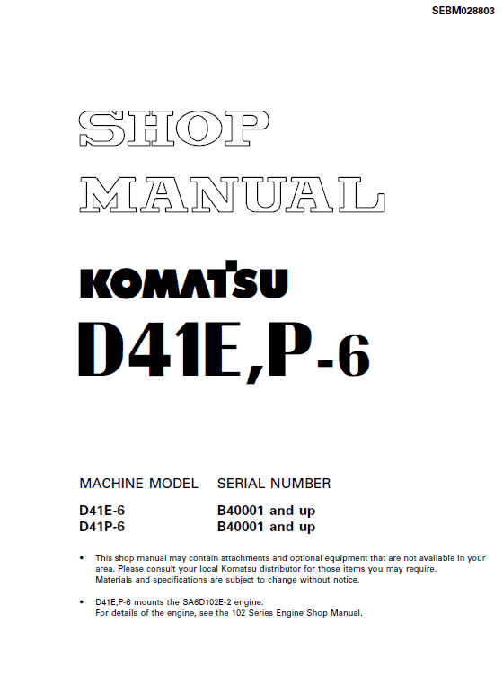
SEBM007009:
B20001 – B40000
50001 and up
SEBD028803:
B40001 and up
Manuals: Shop Manual
01 GENERAL …………………………………………………………………… 01-1
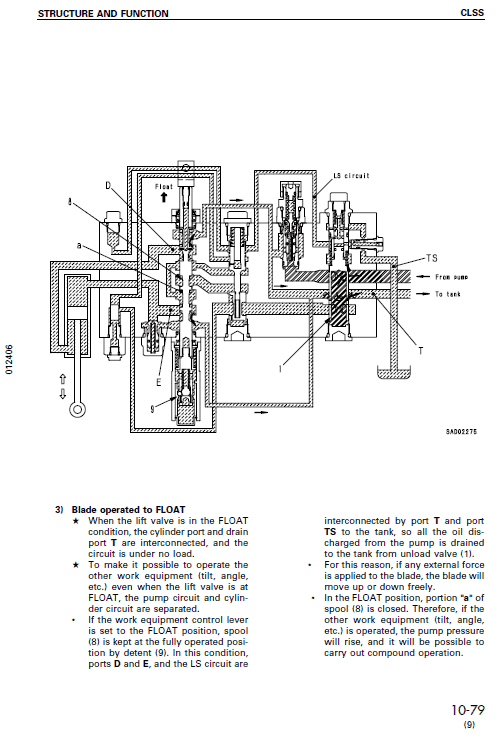
10 STRUCTURE AND FUNCTION……………………………………..10-1
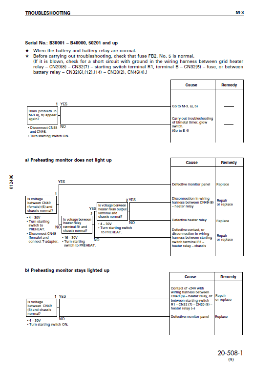
20 TESTING AND ADJUSTING…………………………………………20-1
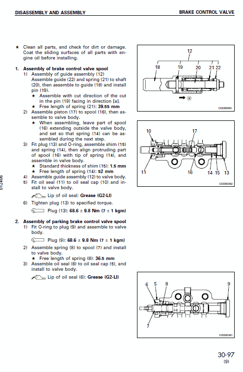
30 DISASSEMBLY AND ASSEMBLY…………………………………30-1
40 MAINTENANCE STANDARD………………………………………..40-1
90 OTHERS …………………………………………………………………….. 90-1
STRUCTURE AND FUNCTION
This section explains the structure and function of each component. It serves not only to give
an understanding of the structure, but also serves as reference material for troubleshooting.
TESTING AND ADJUSTING
This section explains checks to be made before and after performing repairs, as well as adjustments to be made at completion of the checks and repairs. Troubleshooting charts correlating “Problems” to “Causes” are also included in this section.
DISASSEMBLY AND ASSEMBLY
This section explains the order to be followed when removing, installing, disassembling or assembling each component, as well as precautions to be taken for these operations.
MAINTENANCE STANDARD
This section gives the judgement standards when inspecting disassembled parts.
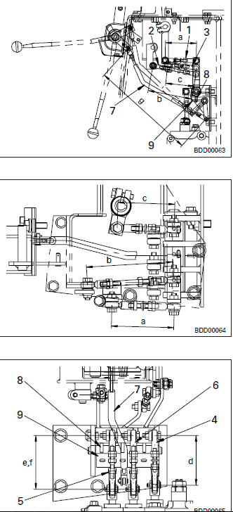
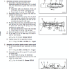
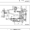
ADJUSTING WORK EQUIPMENT CONTROL LINKAGE AND SAFETY LEVER LINKAGE
1. Adjusting rod at control lever end
1) Adjust so that distance between pins “a” of lift spool rod (1) is the dimension below. * Dimension “a”: 96 mm 2) Adjust so that distance between pins “b” of tilt spool rod (2) is the dimension below. * Dimension “b”: 145 mm 3) Adjust so that distance between pins “c” of angle spool rod (3) is the dimension below. * Dimension “c”: 91 mm 2. Adjusting rod at spool end
1) Adjust so that distance between pins “d” of lift spool rod (4) is the dimension below. * Dimension “d”: 98 mm 2) Adjust so that distance between pins “e” of tilt spool rod (5) is the dimension below. * Dimension “e”: 104.6 mm 3) Adjust so that distance between pins “f” of angle spool rod (6) is the dimension below. * Dimension “f”: 104.6 mm 3. Adjusting safety lever rod
1) Adjust so that distance between pins “g” of safety lever (7) is the dimension below. * Dimension “g”: 345.9 mm 2) Set the safety lever in the LOCK position, and check that pin (8) enters plate (9).
Use publication SEBM007009 and SEBD028803 with the D41E-6, D41P-6 model details to select the appropriate documentation. Refer to 01 GENERAL within its stated document and equipment scope.


Reviews
There are no reviews yet.