
THE MANUAL LIBRARY
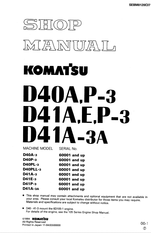
Komatsu D41A-3, D41E-3, D41P-3, D41A-3A Dozer Repair Manual
$33.00
Documentation Specifications
| Manufacturer | Komatsu |
| Applicable Model | D41A-3, D41E-3, D41P-3, D41A-3A |
| Serial Number Range | 60001 and up |
| Machine Type | Dozer |
| Documentation | Repair Manual |
| Publication Reference | SEBM0120C07 |
| Language | English |
| Format |
Manuals Provided
| Repair Manual | 556 pages |
For Komatsu D41A-3, D41E-3, D41P-3, D41A-3A Dozer, this reference brings together the listed repair manual material. Start with 10 ENGINE and follow the relevant document section for the task.
What’s Covered Inside
10 ENGINE
11 STRUCTURE AND FUNCTION . . . . . . . . . . . . . . . . . . . . . . . . . . . . . . . . . . . . . . . . . . . . . . . 11-1
12 TESTING AND ADJUSTING . . . . . . . . . . . . . . . . . . . . . . . . . . . . . . . . . . . . . . . . . . . . . . . . . . 1 2-1
13 DISASSEMBLY AND ASSEMBLY . . . . . . . . . . . . . . . . . . . . . . . . . . . . . . . . . . . . . . . . . . . . . 13-1
20 POWER TRAIN
21 STRUCTURE AND FUNCTION . . . . . . . . . . . . . . . . . . . . . . . . . . . . . . . . . . . . . . . . . . . . . . . 21 -1
22 TESTING AND ADJUSTING . . . . . . . . . . . . . . . . . . . . . . . . . . . . . . . . . . . . . . . . . . . . . . . . . . 22-1
23 DISASSEMBLY AND ASSEMBLY . . . . . . . . . . . . . . . . . . . . . . . . . . . . . . . . . . . . . . . . . . . . . 23-1
24 MAINTENANCE STANDARD . . . . . . . . . . . . . . . . . . . . . . . . . . . . . . . . . . . . . . . . . . . . . . . . . 24-1
30 UNDERCARRIAGE
31 STRUCTURE AND FUNCTION . . . . . . . . . . . . . . . . . . . . . . . . . . . . . . . . . . . . . . . . . . . . . . . 31 -1
33 DISASSEMBLY AND ASSEMBLY . . . . . . . . . . . . . . . . . . . . . . . . . . . . . . . . . . . . . . . . . . . . . 33-1
34 MAINTENANCE STANDARD . . . . . . . . . . . . . . . . . . . . . . . . . . . . . . . . . . . . . . . . . . . . . . . . . 34-1
60 HYDRAULIC SYSTEM
61 STRUCTURE AND FUNCTION . . . . . . . . . . . . . . . . . . . . . . . . . . . . . . . . . . . . . . . . . . . . . . . 61-1
62 TESTING AND ADJUSTING . . . . . . . . . . . . . . . . . . . . . . . . . . . . . . . . . . . . . . . . . . . . . . . . . . 62-1
63 DISASSEMBLY AND ASSEMBLY . . . . . . . . . . . . . . . . . . . . . . . . . . . . . . . . . . . . . . . . . . . . . 63-1
64 MAINTENANCE ST AND ARD . . . . . . . . . . . . . . . . . . . . . . . . . . . . . . . . . . . . . . . . . . . . . . . . . 64-1
70 WORK EQUIPMENT
71 STRUCTURE AND FUNCTION . . . . . . . . . . . . . . . . . . . . . . . . . . . . . . . . . . . . . . . . . . . . . . . 71-1
73 DISASSEMBLY AND ASSEMBLY . . . . . . . . . . . . . . . . . . . . . . . . . . . . . . . . . . . . . . . . . . . . . 73-1
7 4 MAINTENANCE STANDARD . . . . . . . . . . . . . . . . . . . . . . . . . . . . . . . . . . . . . . . . . . . . . . . . . 7 4-1
90 ELECTRIC AND ELECTRONIC SYSTEM
90 ELECTRONIC SYSTEM . . . . . . . . . . . . . . . . . . . . . . . . . . . . . . . . . . . . . . . . . . . . . . . 90-1
STRUCTURE AND FUNCTION
This section explains the structure and function of each component. It serves not only to give
an understanding of the structure, but also serves as reference material for troubleshooting.
TESTING AND ADJUSTING
This section explains checks to be made before and after performing repairs, as well as adjustments to be made at completion of the checks and repairs. Troubleshooting charts correlating “Problems” to “Causes” are also included in this section.
DISASSEMBLY AND ASSEMBLY
This section explains the order to be followed when removing, installing, disassembling or assembling each component, as well as precautions to be taken for these operations.
MAINTENANCE STANDARD
This section gives the judgement standards when inspecting disassembled parts.
INTAKE AND EXHAUST ENGINE SYSTEM
CLOGGING OF AIR CLEANER ELEMENT
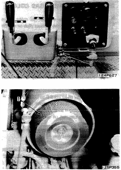
1. Checking dust indicator
Check if dust indicator (1) has reached service level (red). * The dust indicator is actuated by the increase in intake pressure caused by clogging of the element, etc. When this negative pressure reaches 635 mmAq, a red piston moves into sight.
2. Directly checking air cleaner element When the dust indicator is red, or the exhaust gas is black, check the element as follows.
1) Loosen clamp and remove dust cap.
2) Remove wing nut, then remove outer element (1) and check for clogging. * When checking, cleaning or replacing the element, be careful not to let dust enter the element case.
3) After checking or cleaning outer element, push button of dust indicator to return red piston to original position.
Use publication SEBM0120C07 with the D41A-3, D41E-3, D41P-3, D41A-3A model details to select the appropriate documentation. Refer to 10 ENGINE within its stated document and equipment scope.
Reviews
There are no reviews yet.