
The 2018 Hino COE/HEV listing identifies 155, 155h, 195 and 195h models. It lists 2018 truck and owner manuals, a troubleshooting manual explicitly labelled 2017, and a J05E engine manual; the sample concerns differential-carrier inspection.
Document Details
Hino 2018 COE HEV Truck Manual for 155, 155h, 195, 195h Series – 890 Pages
Hino 2018 Owners Manual – 424 Pages
Troubleshooting Manual for Hino 2017 COE HEV – 886 Pages
Hino J05E Engine Manual – 668 Pages
This is the Repair and Service Manual for Hino Truck 2018 COE HEV
Applicable for HINO 155, 155h, 195, 195h series,
This workshop manual has been prepared to provide information covering repairs on 155, 155h, 195, 195h Series Hino 2018 COE HEV trucks.
Contents Listed
General Introduction
Engine
Hybrid System
Transmission
Clutch
Propeller Shaft
Axle
Differential
Brake
Steering
Frame and Frame Accessory
Cab Mounting and Cab Suspension
Body Construction
Suspension
Body Inside Accessory
Body Outside Accessory
Air Bag and Seat Belt
Heater and Air Conditioner
Electrical
Control System
Procedure Excerpt
Hino Truck 2018 COE HEV Manual Instruction Extract:
INSPECTING THE DIFFERENTIAL CARRIER ASSEMBLY
1. INSPECTING THE SIDE GEAR AND RING GEAR.
(1) Inspect the side gear and ring gear for wear and damage. If any defect is found, replace the part.
NOTICE
When replacing the ring gear, replace the drive pinion of the drive pinion assembly as a set.
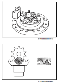
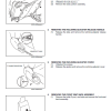
2. INSPECTING THE DIFFERENTIAL SPIDER (1) Using a micrometer, measure the outer diameter of the differential spider.
(2) Using a dial caliper gauge, measure the inner diameter of the differential pinion.
(3) Subtract the differential spider outer diameter from the differential pinion inner diameter to compute the gap. If it exceeds the limit,replace the differential spider and the differential pinion.
5. INSPECTING THE BACKLASH BETWEEN
THE DIFFERENTIAL PINIONS AND SIDE GEARS
(1) Install the side gear thrust washers No.1 and the side gears onto the left hand side differential case.
(2) Install the differential pinions (4 pcs.) and the pinion thrust washers (4 pcs.) to the differential spider.
(3) Install the differential spider, assembled with the differential pinions and pinion thrust washers, onto the left hand side differential case.
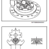
(4) As shown in the figure, set the dial gauge onto the left hand side differential case.
(5) Measure the backlash when the side gear and differential pinion are in position as shown in the figure.
(6) If the measurement exceeds the standard value, replace the parts.
(7) Using the same method, measure the backlash between the side gears and the differential pinions on the right hand side differential case side.
The 886-page troubleshooting manual retains its supplied 2017 label within this 2018 listing.
Match each listed document to its model and year. Read procedure excerpts within the full manual section and use the referenced safety instructions; tools mentioned in a procedure are not included with the documentation.


Reviews
There are no reviews yet.