
The 2015 Hino Conventional listing covers 238, 258LP, 268 and 338 models through separate truck, owner, troubleshooting and J08E engine-manual entries. A clutch sample distinguishes release-bearing position from free-travel adjustment.
Document Details
Hino 2015 Conventional Truck Manual for 238, 258LP, 268, 338 Series – 1006 Pages
Hino 2015 Conventional Owners Manual – 466 Pages
Troubleshooting Hino 2015 Manual – 612 Pages
Hino J08E-VB and J08E-VC Engine Manual – 344 Pages
This is the Repair and Service Manual for Hino Truck 2015
Applicable for 238, 258LP, 268, 338 Series
This workshop manual has been prepared to provide information covering repairs on 238, 258LP, 268, 338 Series Hino 2015 Conventional trucks.
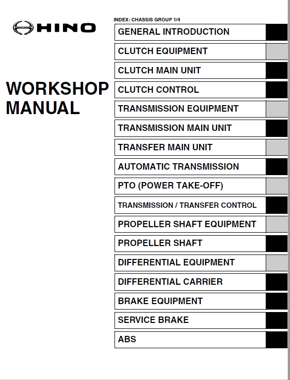
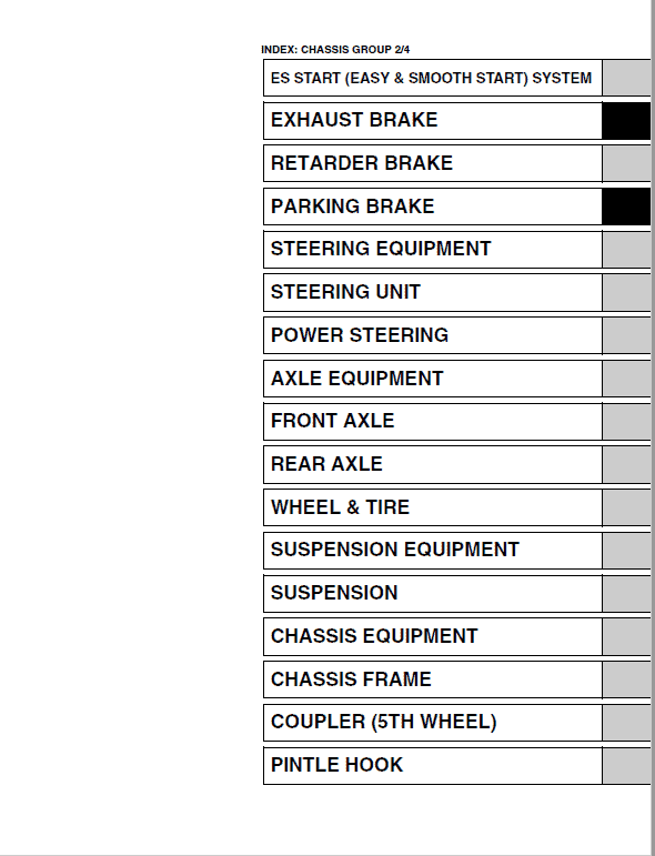
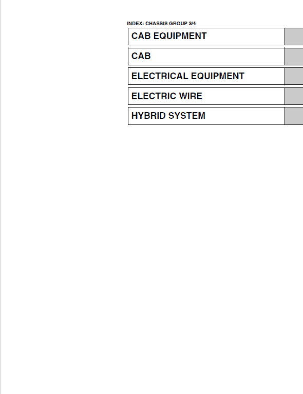
Contents Listed
General Introduction
Clutch Equipment
Clutch Main Unit
Clutch Control
Transmission Equipment
Transmission Main Unit
Transfer Main Unit
Automatic Transmission
P.t.o. (Power Take-off)
Transmission / Transfer Control
Propeller Shaft
Differential Equipment
Differential Carrier
Index: Chassis Group 1/4
Propeller Shaft Equipment
Brake Equipment
Service Brake
Abs & Asr
Es Start (Easy & Smooth Start) System
Exhaust Brake
Retarder Brake
Parking Brake
Steering Equipment
Steering Unit
Power Steering
Axle Equipment
Front Axle
Rear Axle
Wheel & Tire
Suspension Equipment
Suspension
Chassis Equipment
Chassis Frame
Coupler (5th Wheel)
Pintle Hook
Cab Equipment
Cab
Electrical Equipment
Electric Wire
Hybrid System
Procedure Excerpt
Hino Truck 2015 Conventional Manual Instruction Extract:
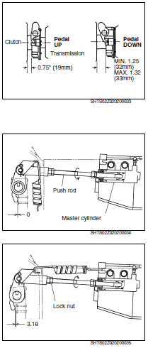
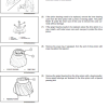
4. ADJUST THE RELEASE BEARING POSITION
(1) Set 0.75″ (19 mm) dimension: With pedal down, turn adjusting ring to obtain approximately 0.75″ (19 mm). Turning the adjusting ring clockwise moves the release bearing toward the transmission. Turning the adjusting ring counterclockwise moves the release bearing toward the engine.
(2) Check release travel dimensions with release yoke rotated toward release bearing, eliminating excess play in system. Having set this, depress pedal down fully releasing clutch and check release travel to settings shown.
NOTICE
It may be necessary to reduce the 0.75″ (19 mm) settings to be able to achieve 0.500″-0.562″ (13-14 mm) travel on some models of transmissions.
5. ADJUST THE FREE TRAVEL
(1) Remove the return spring.
(2) Loosen the lock nut and turn the push rod counterclockwise until the release bearing contacts the release lever plate or release lever.
(3) Turn the push rod clockwise about 3 1/3 turns.
Standard: Clearance between release bearing and release yoke: 3.18 mm {0.125 in.}
(4) Tighten the lock nut.
Match each listed document to its model and year. Read procedure excerpts within the full manual section and use the referenced safety instructions; tools mentioned in a procedure are not included with the documentation.


Reviews
There are no reviews yet.