
THE MANUAL LIBRARY
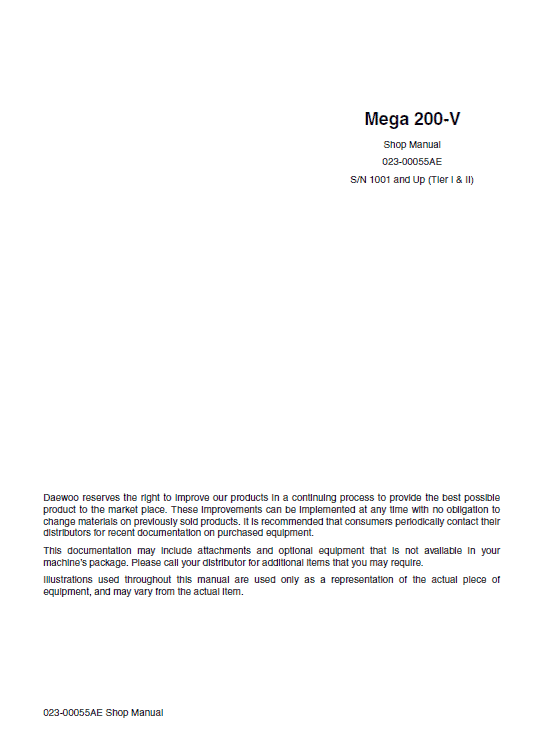
Daewoo Doosan Mega 200-V Repair Manual PDF – 023-00055AE
$33.00
Documentation Specifications
| Manufacturer | Doosan |
| Applicable Model | M200-V |
| Serial Number Range | S 1001 and Up (Tier I & II) |
| Machine Type | Loader |
| Documentation | Repair Manual |
| Publication Reference | 023-00055AE |
| Language | English |
| Format |
Manuals Provided
| Repair Manual | 584 Pages |
For Doosan M200-V Wheel Loader, this reference brings together the listed repair manual material. Start with Safety and follow the relevant document section for the task.
What’s Covered Inside
Safety
Wheel Loader Safety ……………………………………………………………….. S0103010K
Specifications
Specifications for Mega 200-V……………………………………………………S0203100C
General Maintenance
General Maintenance Procedures…………………………………………………S0302000
Standard Torques……………………………………………………………………….S0309000
Upper Structure
Counterweight…………………………………………………………………………. S0403030K
Fuel Transfer Pump…………………………………………………………………….S0405500
Hydraulic Oil Tank ……………………………………………………………………S0406060C
Lower Structure and Chassis
Center Joint (Articulation Joint)…………………………………………………..S0502040C
Engine and Drive Train
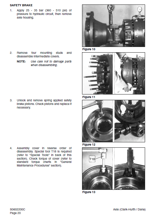
Axle (Clark-Hurth / Dana) ………………………………………………………….S0602200C
Parking Brake (DANA)……………………………………………………………… S0603005K
Air Conditioner ………………………………………………………………………… S0605050K
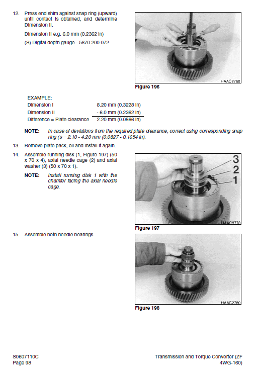
Transmission and Torque Converter (ZF 4WG-160) ……………………..S0607110C
Transmission Error Codes (ZF) ………………………………………………….S0607900C
Hydraulics
Hydraulic System…………………………………………………………………….. S0702035K
Accumulator……………………………………………………………………………. S0703010K
Cylinders………………………………………………………………………………… S0705015K
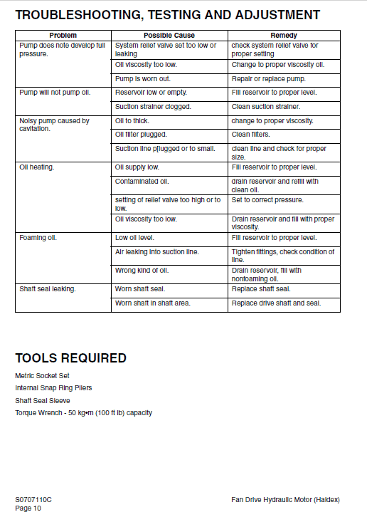
Fan Drive Hydraulic Motor (Haldex) ……………………………………………S0707110C
Main Pump (Parker)………………………………………………………………….S0708510C
Brake Pedal Valve ……………………………………………………………………S0709260C
Main Control Valve (Husco)……………………………………………………….S0709457C
Pilot Control Valve ……………………………………………………………………S0709478C
Priority Valve………………………………………………………………………………S0709650
Power Steering Unit………………………………………………………………….S0709705C
Restriction Valve………………………………………………………………………S0709752C
Hydraulic Schematic (Mega 200-V) …………………………………………….S0793015C
Electrical System
Electrical System ……………………………………………………………………..S0802015C
Electrical Schematic (Mega 200-V) …………………………………………….S0893015C
Instruction
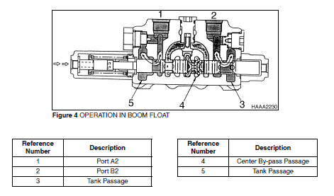
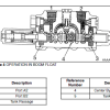
When the control lever is further pushed down from the Down position to the Float position, the boom spool moves as indicated in the illustration.
Due to this motion the neutral passage is opened. The pressure oil flows as if in neutral position. The cylinder ports (A2) and (B2) are connected to the low-pressure oil passage. As a result, the booms float over the ground surface according to its irregularities. The oil discharged from the boom cylinder rod side is sent to the tail side and the oil forced out from its tail side is sent to the rod side respectively through the low-pressure oil passage in the control valve.
RELIEF VALVE
Main Relief Valve
The main relief valve is located between the neutral oil passage and the low pressure oil passage (return oil passage) in the inlet section.
Port Relief Valve
The port relief valve is located between the rod side cylinder port and the low-pressure oil passage (return oil passage) in the bucket spool section.
The combination valve, used as the port relief valve, serves both as the relief valve and an anticavitation valve.
How to Use The Guide Manual
A schematic of each of the major engine systems is provided at the beginning of the section of the manual devoted to troubleshooting and repairing that particular system.
Basic safety precautions are list in the Safety section of the Service Manual. Additional safety precautions are list in the Safety section of the owner/operation/maintenance publication. Specific safety warnings for all these publications are provided in the description of operations where hazards exist. WARNING labels have also been put on the product to provide instructions and to identify specific hazards.
Use publication 023-00055AE with the M200-V model details to select the appropriate documentation. Refer to Safety within its stated document and equipment scope.
Reviews
There are no reviews yet.