
Repair documentation for the Doosan DX380LC-3 covers structural, hydraulic, electrical and attachment systems. Its engine and drivetrain contents list the optional coolant heater and main-pump drive coupling; the separate burner-head passage is a heater-service excerpt.
Document Details
Manuals: Shop Manual
Contents Listed
Safety
Track Excavator Maintenance Safety SP002322
Specifications
Specification for DX380LC-3 SP002604
General Maintenance
General Maintenance Instructions SP002454
Standard Torques SP002404
Upper Structure
Cabin SP002324
Counterweight SP002606
Fuel Tank SP002410
Fuel Transfer Pump (Option) SP002394
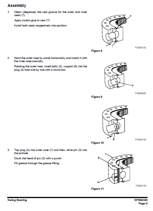
Swing Bearing SP002329
Lower Structure and Chassis
Track Assembly SP002607
Engine and Drivetrain
Engine Coolant Heater (Option) SP002328
Drive Coupling (Main Pump) SP002411
Hydraulics
Hydraulic System Troubleshooting, Testing and Adjustment SP002412
Accumulator SP002455
Center Joint (Swivel) SP002545
Cylinders SP002422
Swing Device SP002413
Travel Device SP002609
Main Pump SP002415
Gear Pump SP002568
Fan Motor for Oil Cooler SP002552
Fan Pump SP002553
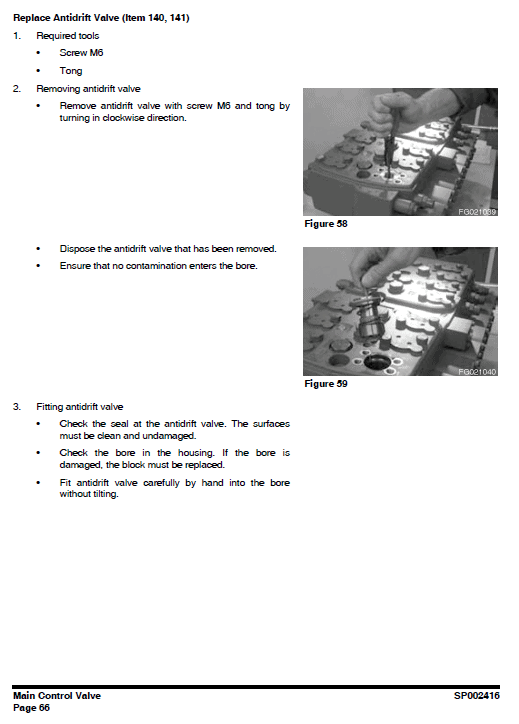
Main Control Valve SP002416
Remote Control Valve (Work Lever / Joystick) SP002450
Travel Control Valve (with Damper) SP002381
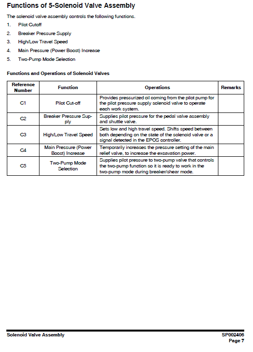
Solenoid Valve Assembly SP002406
Breaker EPPR Valve (Option) SP002458
Hydraulic Schematic SP002610
Electrical System
Electrical System SP002418
Electrical Schematic SP002419
Attachments
Boom and Arm SP002605
Bucket SP002421
Procedure Excerpt
Changing the Burner Head
Removal
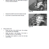
1. Remove heater.
2. Remove combustion air fan.
3. Remove burner, flame monitor and glow plug.
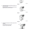
4. Remove mounting screw of the V-clamping collar (2, Figure 6) and pull off the clamping collar.
5. Pull out and remove burner head (1, Figure 6) from the heat exchanger (3, Figure 6).
6. Complete the work on stripped-down components.
Installation
NOTE: The burner head and exhaust outlet port can also be aligned during installation in the machine.
1. Guide the burner head (1, Figure 6) into the heat exchanger (3, Figure 6), align it if necessary and secure with the V-clamping collar (2, Figure 6).
2. If necessary, tighten the mounting screw of the V-clamping collar to 3 Nm 10%.
3. Install the burner, flame monitor and glow plug.
4. Attach the combustion air fan.
5. Install the heater.
Match the model, serial number and publication reference before using the manual. Procedure excerpts retain their original figure and page references and should be read within the complete manual section.


Reviews
There are no reviews yet.