
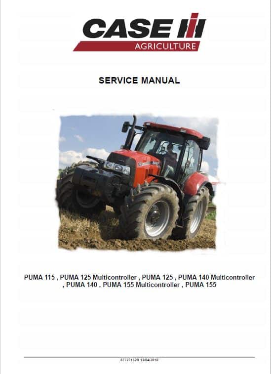
For Case Puma 115, 125, 140, 155 Tractor, this reference brings together the listed repair manual material. Start with Hydraulic and follow the relevant document section for the task.
What’s Covered Inside
Table of Content (Service Manual)
Introduction
Hydraulic
Pneumatic
Electrical
Electronic System
Engine
PTO
Transmission
Drive and PTO out
Axles
Brakes and Steering
Frame and Cab
Hitch and Working Tool
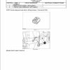
Manual Extract: PRIMARY HYDRAULIC POWER SYSTEM Electro-hydraulic remote valve
Static description Activity
Each remote valve has its own built in microprocessor which controls the oil flow through a solenoid activated valve, based on inputs received from the operator controlled switches.
Each remote valve is connected into the electrical CAN BUS system to the RK / RL control module, located behind the drivers seat. Each remote valve can also detect system faults and send a message to the RK / RL module which in turn sends a signal to allow a fault code to be displayed on the instrument cluster.
Refer to the fault code list for relevant information.
Control Levers
The electro-hydraulic remote valves are operated by control levers in the right-hand console. Each control lever is coloured to correspond to the color on the remote valve. A maximum of four electro-hydraulic remote valves may be fitted.
Use publication 87727132BNA (April 2010) with the Puma 115, 125, 140, 155 model details to select the appropriate documentation. Refer to Hydraulic within its stated document and equipment scope.


Reviews
There are no reviews yet.