
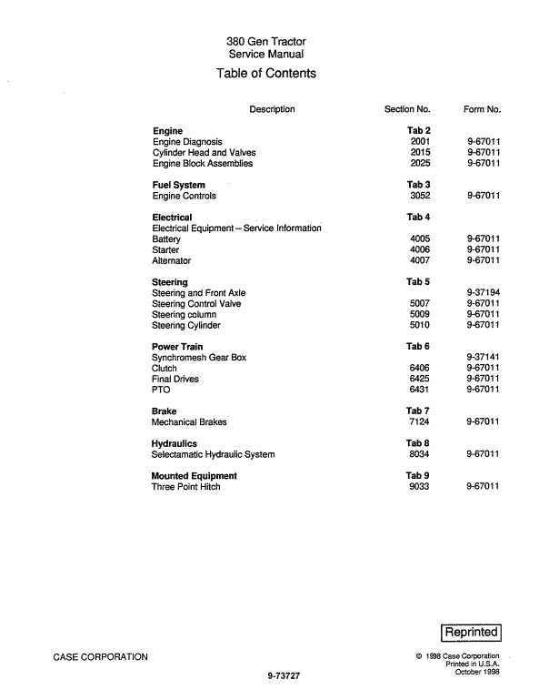
For Case 380 Tractor, this reference brings together the listed repair manual material. Start with General and follow the relevant document section for the task.
What’s Covered Inside
General
Engine
Fuel System
Electrical
Steering
Power Train
Brakes
Hydraulics System
Mounted Equipment
Manual Extract: ALTERNATOR CHARGING CIRCUIT
The alternator charging circuit consists of the battery, alternator with self contained voltage regulator, key switch, alternator warning light, and related wiring. The circuit is schematically illustrated in Figure 1.
The alternator components are the front frame assembly, rear frame assembly, rotor, stator, voltage regulator, and rectifier assembly which contains the diodes.
When the key switch is turned on, battery current flows through the alternator warning light and through the brushes to the rotor windings. This causes the Case 380 alternator warning light to light and provides initial current to the rotor (field) windings.
When the engine is started, the revolving rotor induces current in the stator windings and this is fed into the rotor windings. As increased current through the rotor windings results in a further increase in current generated by the stator windings, a rapid buildup of current takes place.
When voltage produced by the stator windings is greater than the voltage of the battery, current flows to the battery and the alternator warning light is extinguished to show that battery charging is taking place. The diode pack in the rectifier changes the alternating current (A.C.) generated in the stator windings so that direct current (D.C.) is supplied to the battery and rotor windings.
Use publication 9-73727 (Oct 1998) with the 380 model details to select the appropriate documentation. Refer to General within its stated document and equipment scope.


Reviews
There are no reviews yet.