
For Case SV212D, SV216D Vibratory Roller, this reference brings together the listed repair manual material. Start with Maintenance and follow the relevant document section for the task.
What’s Covered Inside
Manuals: Service Manual
Introduction
Maintenance
Engine
Hydrostatic Drive
Hydraulic System
Frames and Ballasting
Steering
Cab Climate Control
Electrical System
Platform, Cab, Bodywork and Decals
Special Index Tools
Electrical Schematics
Hydraulic Schematics
Manual Extract: Compaction front drum – Install
NOTE: For more details refer to Compaction front drum – Component identification (44.160).
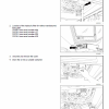
1. Place the frame on suitable supports on both sides.
Hang the drum and lift it by using adequate lifting equipment, and mount it into the frame so that the drum does not bump into the frame.
2. Make sure that there is a gap of 22.0 – 26.0 mm (0.9 – 1.0 in) between the frame and the drum on both sides.
3. Screw the bracket on the right side to the frame. If it is necessary, use shims.
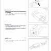
4. Slacken the bolts on the left side of the drum.
5. Mount the weight to the frame and then retighten it by means of bolts.
6. Using a square, measure the distance between the drum and frame near the joint at various places (refer to figure 6). The drum must be axially centered.
7. Lift up the drum and remove the supports.
Introduction
Maintenance
Engine
Hydrostatic Drive
Hydraulic System
Frames and Ballasting
Steering
Cab Climate Control
Electrical System
Platform, Cab, Bodywork and Decals
Special Index Tools
Electrical Schematics
Hydraulic Schematics
Manual Extract: Compaction front drum – Install
NOTE: For more details refer to Compaction front drum – Component identification (44.160).
1. Place the frame on suitable supports on both sides.
Hang the drum and lift it by using adequate lifting equipment, and mount it into the frame so that the drum does not bump into the frame.
2. Make sure that there is a gap of 22.0 – 26.0 mm (0.9 – 1.0 in) between the frame and the drum on both sides.
3. Screw the bracket on the right side to the frame. If it is necessary, use shims.
4. Slacken the bolts on the left side of the drum.
5. Mount the weight to the frame and then retighten it by means of bolts.
6. Using a square, measure the distance between the drum and frame near the joint at various places (refer to figure 6). The drum must be axially centered.
7. Lift up the drum and remove the supports.
Use publication 51429076 (April 2018) with the SV212D, SV216D model details to select the appropriate documentation. Refer to Maintenance within its stated document and equipment scope.


Reviews
There are no reviews yet.