
For Case DV209C, DV210C Vibratory Roller, this reference brings together the listed repair manual material. Start with Machine completion and equipment and follow the relevant document section for the task.
What’s Covered Inside
Manuals: Service Manual
Introduction
Machine completion and equipment
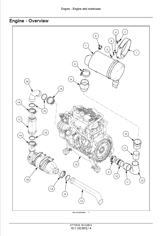
Engine
Hydrostatic Drive
Hydraulic System
Frames and Ballasting
Steering
Wheels
Cab Climate Control
Electrical System
Platform, Cab, Bodywork and Decals
Manual Extract: Brake pump – Check
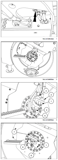
NOTE: The below procedure shows the removal of the rear travel motor (located on the right-hand side of the drum).
The procedure is the same to remove the front travel motor (located on the left-hand side of the drum).
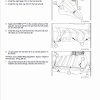
1. Place a suitable drain collector with adequate capacity under the frame.
NOTICE: Approximate drain volume: 60 L (16 US gal).
2. Remove the drain plug and drain the hydraulic oil.
3. Supports the frame on both the sides.
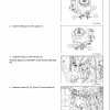
4. Place suitable drain collectors with adequate capacity under the travel motor to be removed.
5. Drain the oil form the travel reduction gear.
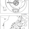
6. Remove the hose (2) and (3) from the travel motor (1).
7. Remove the hose (4) and (5) from the travel motor (1).
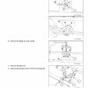
8. Cover the ports with protective plugs.
9. Remove the bolts (6).
10. Remove the travel motor (1).
11. If the motor needs to be replaced, remove the flanges (7) from the motor (1).
Introduction
Machine completion and equipment
Engine
Hydrostatic Drive
Hydraulic System
Frames and Ballasting
Steering
Wheels
Cab Climate Control
Electrical System
Platform, Cab, Bodywork and Decals
Manual Extract: Brake pump – Check
NOTE: The below procedure shows the removal of the rear travel motor (located on the right-hand side of the drum).
The procedure is the same to remove the front travel motor (located on the left-hand side of the drum).
1. Place a suitable drain collector with adequate capacity under the frame.
NOTICE: Approximate drain volume: 60 L (16 US gal).
2. Remove the drain plug and drain the hydraulic oil.
3. Supports the frame on both the sides.
4. Place suitable drain collectors with adequate capacity under the travel motor to be removed.
5. Drain the oil form the travel reduction gear.
6. Remove the hose (2) and (3) from the travel motor (1).
7. Remove the hose (4) and (5) from the travel motor (1).
8. Cover the ports with protective plugs.
9. Remove the bolts (6).
10. Remove the travel motor (1).
11. If the motor needs to be replaced, remove the flanges (7) from the motor (1).
Use publication 47772910 (Oct 2014) with the DV209C, DV210C model details to select the appropriate documentation. Refer to Machine completion and equipment within its stated document and equipment scope.


Reviews
There are no reviews yet.