
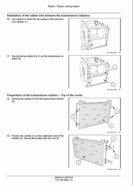
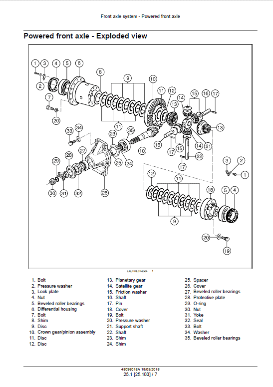
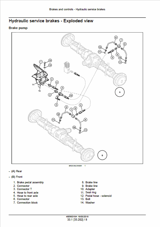
The Case W20F wheel-loader service manual is listed at 859 pages under publication 48096018A, dated May 2018. Its powered rear-axle installation sample retains the separate stabilizer, pivot-pin, drive-shaft and wheel fastening instructions.
Document Details
Manuals: Service Manual
Contents Label
Content
Contents Listed
Introduction
Engine
Main Gearbox and Drive
Transmission
Front Axle
Rear Axle
Hydrostatic Drive
Brakes and Controls
Hydraulic System
Steering
Wheels
Cab climate control
Electrical System
Booms, dippers and buckets
Platform, Cab, Bodywork and Decals
Special Tool Index
Procedure Excerpt
Manual Extract: Powered rear axle – Install
Installation
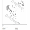
1. If the bushings have been removed from the stabilizer, fit new bushings that are level with the stabilizer’s outer surfaces.
2. If the stabilizer has been removed from the axle, mount it on the axle and torque the axle mounting bolts to 705 – 868 N·m (520 – 640 lb ft).
3. Place the stabilizer and axle assembly under the machine.
4. Suspend the stabilizer and axle assembly until the stabilizer is in position and the holes in it are aligned with the holes in the rear chassis.
5. Fit the pins and washers into the stabilizer, so that the threaded part of the front stabilizer pin is facing the front of the machine and the threaded part of the rear stabilizer pin is facing the rear.
6. Mount the washer and self-locking nut on each stabilizer pin.
7. Torque the self-locking nuts to 542 – 678 N·m (400 – 500 lb ft).
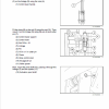
8. Connect the lubrication hoses to the fittings on the stabilizer pins.
9. Connect the brake tubing hose to the adapter on the rear axle.
10. Install the drive shaft. Torque the nuts securing the drive shaft to the shaft coupling flange and the switch box flange to 54 – 74 N·m (40 – 55 lb ft).
11. Fit the wheels and torque the nuts to 515 – 569 N·m (380 – 420 lb ft).
12. Lubricate the stabilizer’s linkage points with Akcela molybdenum disulfide.
13. Idle the engine.
14. Test the brakes (see Section 7001).
NOTE: Every two hours of operation, do the following: A. Tighten the retaining nuts on the axle to 705 – 868 N·m (520 – 640 lb ft), until the torque stabilizes.
B. Tighten the wheel nuts to 515 – 569 N·m (380 – 420 lb ft), until the torque stabilizes.
Match the listed manual to the machine and publication reference. Page counts and publication references remain separately listed where the source does not pair them. Procedure samples retain their component names, notices and diagram references; use them within the full manual section. Referenced tools are not supplied with the documentation.


Reviews
There are no reviews yet.