
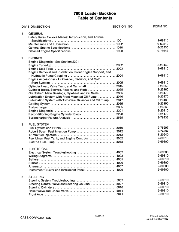
The Case 780B loader backhoe service manual covers engines, fuel and electrical systems, steering, power train, brakes, hydraulics and mounted equipment. Its sample passage addresses removal of circuit-relief and check-valve hose connections.
Document Details
Manuals: Service Manual
Contents Listed
General
Engines
Fuel System
Electrical
Steering
Power Train
Brakes
Hydraulics
Mounted Equipment
Procedure Excerpt
Manual Extract: Circuit Relief and Check Valve Hose Connections Removal
1. Park the machine on a level surface.
2. Raise the loader bucket.
3. Put the loader strut into position.
4. Apply the parking brake. Stop the engine.
5. Remove the left and right side panels from the engine compartment.
6. If a vacuum pump is available, connect the vacuum pump to the hydraulic reservoir to keep the hydraulic fluid in the hydraulic reservoir. If a vacuum pump is not available, do the following steps:
a. Slowly loosen the fill cap for the hydraulic reservoir to release any air pressure.
b. Remove the fill cap from the hydraulic reservoir.
c. Put a clean container under the drain plug for the hydraulic reservoir. The hydraulic reservoir holds approximately 19 U.S. gallons (72 liters) of hydraulic fluid.
d. Remove the drain plug from the hydraulic reservoir and drain the hydraulic reservoir.
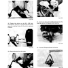
7. Disconnect the hoses from the check valves and the circuit relief valve. Put identification tags on the hoses.
8. Install caps and plug on the hoses and fittings to prevent contamination of the hydraulic system.
9. Remove the nuts, lock washers, washers, and bolts that hold the circuit relief valve to the mounting bracket.
10. Remove the check valves and circuit relief valve from the machine.
Match the machine model and publication reference before using the manual. Read the procedure excerpt within its complete manual section, including the referenced precautions and specifications.


Reviews
There are no reviews yet.