
For Case 1021G, 1121G Wheel Loader, this reference brings together the listed repair manual material. Start with Engine and follow the relevant document section for the task.
What’s Covered Inside
Manuals: Service Manual
Introduction
Engine
Transmission
Four Wheel Drive
Front Axle
Rear Axle
Brakes and Controls
Hydraulic System
Brakes and Controls
Frames and Ballasting
Steering
Wheels
Cab climate control
Electrical System
Front Loader and Bucket
Platform, Cab, Bodywork and Decals
Special Tool Index
Manual Extract: Oil cooler/Heat exchanger – Remove
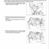
1. Park the machine on a level surface and lower the bucket to the ground. Stop the engine and apply the parking brake.
2. Raise the engine hood.
3. Place the timed disconnect switch in the OFF position.
4. Open the frame of the engine cooling system.
5. Loosen the filler cap on the hydraulic reservoir to release the air pressure in the reservoir. Connect a vacuum pump to the hydraulic reservoir, turn on the pump.
6. Disconnect the top hose and install a plug in the hose and a cap on the fitting.
7. Disconnect the hose from the bottom of the oil cooler.
Install a plug in the hose and a cap on the fitting.
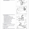
8. Loosen and remove the bolts (1) and the washers (2) that fasten the oil cooler to the cooling frame. Remove the oil cooler from the machine.
Introduction
Engine
Transmission
Four Wheel Drive
Front Axle
Rear Axle
Brakes and Controls
Hydraulic System
Brakes and Controls
Frames and Ballasting
Steering
Wheels
Cab climate control
Electrical System
Front Loader and Bucket
Platform, Cab, Bodywork and Decals
Special Tool Index
Manual Extract: Oil cooler/Heat exchanger – Remove
1. Park the machine on a level surface and lower the bucket to the ground. Stop the engine and apply the parking brake.
2. Raise the engine hood.
3. Place the timed disconnect switch in the OFF position.
4. Open the frame of the engine cooling system.
5. Loosen the filler cap on the hydraulic reservoir to release the air pressure in the reservoir. Connect a vacuum pump to the hydraulic reservoir, turn on the pump.
6. Disconnect the top hose and install a plug in the hose and a cap on the fitting.
7. Disconnect the hose from the bottom of the oil cooler.
Install a plug in the hose and a cap on the fitting.
8. Loosen and remove the bolts (1) and the washers (2) that fasten the oil cooler to the cooling frame. Remove the oil cooler from the machine.
Use publication 48083742 (Jul 2018), 51428221 (Nov 2017) & 51428268 (Dec 2017) with the 1021G, 1121G model details to select the appropriate documentation. Refer to Engine within its stated document and equipment scope.


Reviews
There are no reviews yet.