
For Case 680CK, 680CK Series C, 680CK Series E Loader, this reference brings together the listed repair manual material. Start with 10 SERIES – GENERAL and follow the relevant document section for the task.
What’s Covered Inside
Service Manual: 498 Pages
680CK Series C
Service Manual: 623 Pages
Operators Manual: 124 Pages
680CK Series E
Service Manual: 706 Pages
Manuals: Service Manual
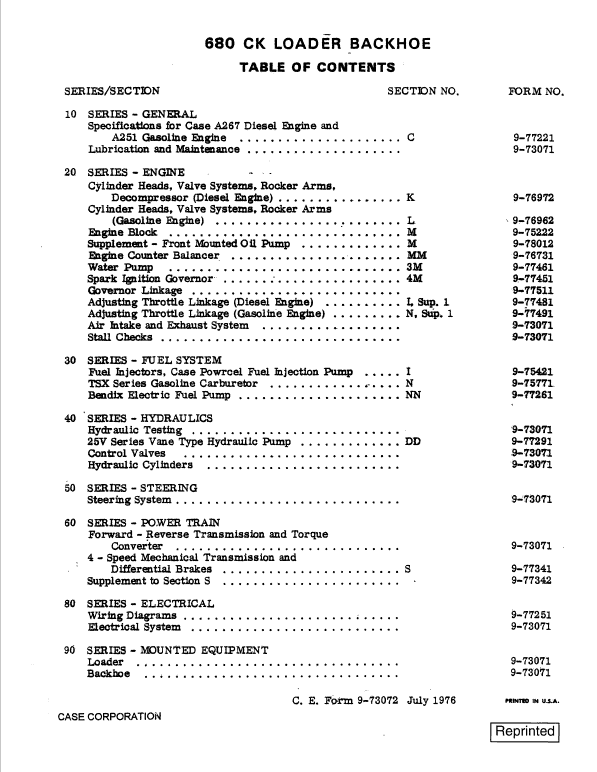
Table of Contents – 680 CK Series C Service Manual
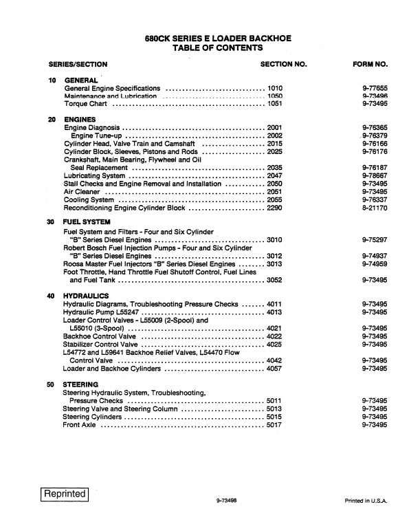
10 SERIES – GENERAL
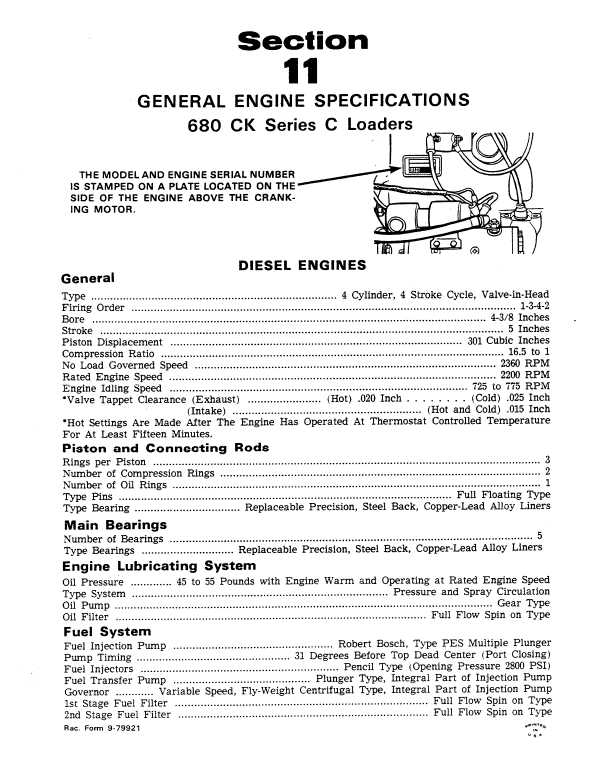
General Engine Specifications
Maintenance and Lubrication
Torque Chart
20 SERIES – ENGINES
Cylinder Head and Valves
Engine Block Assembly
Water Pump, Thermostats, Oil Cooler, and Filters
Engine Removal and Stall Checks
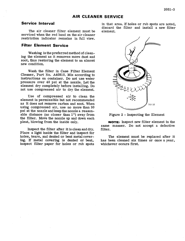
Air Cleaner
30 SERIES – FUEL SYSTEM
Fuel System and Filters
Fuel Injection Pumps
Roosa-Master Fuel Injectors
Electric Fuel Pump
Fuel Lines and Throttle Adjustment
40 SERIES – HYDRAULICS
Hydraulic Diagrams, Trouble Shooting, Pressure Checks
Hydraulic Pump
Loader Control Valve
Case Backhoe Control Valve
Commercial-Shearing Backhoe Control Valve
Extendahoe Control Valve
Stabilizer Lock Valve
Hydra-Guide
Boom Lockout Valve and Relief Valve
Loader and Backhoe Cylinders
NOTE: Also see Sections 9011 and 9012 for exploded views of hydraulic system.
50 SERIES – STEERING
Hydraulic Diagram, Trouble Shooting, Pressure Check
Steering Pump
Steering Valve and Column
Steering Cylinders
Front Axle
60 SERIES – POWER TRAIN
Transmission/Converter Hydraulic Diagram, Operation and Description
Trouble Shooting and Testing
Forward-Reverse Transmission (Power Shuttle)
Four Speed Mechanical Transmission
Rear Axle
Drive Shaft
70 SERIES – BRAKES
Air System Diagrams, Operation, Pressurizing/Depressurizing the Air System, and Trouble Shooting
Foot Brakes and Slack Adjuster
Air Compressor, Governor, Reservoir, Moisture Ejection Valve
Brake Valve
Brake Actuator
Parking Brake Control Valve and Quick Release Valve
Pressure Reducing Valve, Pressure Protection Valve
Double Check Valve, Clutch Cutout Valve, Stoplight Switch
Alcohol Evaporator
80 SERIES – ELECTRICAL
Wiring Diagrams
Trouble Shooting and Adjustments
Batteries
Starter and Starter Solenoid
Alternator
90 SERIES – MOUNTED EQUIPMENT
Loader
Backhoe
ROPS Cab and Canopy
Front Floor Plate Assembly
Manual Extract Cylinder Check
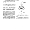
a. If checking loader lift cylinders, drive the machine onto blocks that are high enough to completely retract the lift cylinders. Completely retract the lift cylinders and shut off engine. Remove the tube to the closed end of a lift cylinder.
b. If checking the tilt cylinders, completely retract the tilt cylinders and shut off engine. Disconnect the hose at the closed end of one of the cylinders.
c. To check any other cylinder, run cylinder to end of stroke. Shut off engine. Provide supports to prevent collapse of attachment (if required), then disconnect hose or tube on the return side of the cylinder.
d. Start the engine and run at half throttle. Move the control lever into the same position as in step 2a, 2b, or 2c, and hold in place. System pressure will now rise to the setting of the main relief valve. Check for leakage through the open line. Any leakage indicates worn cylinder packing; however, slight leakage is permissible.
e. If leakage is found, remove the defective cylinder and repair. Recheck circuit operation. If the problem is not completely remedied, there is additional leakage in the control valve.
Use publication 9-2762 & 9-72595 & 9-73072 & 9-73498 with the 680CK, 680CK Series C & 680CK Series E model details to select the appropriate documentation. Refer to 10 SERIES – GENERAL within its stated document and equipment scope.


Reviews
There are no reviews yet.