
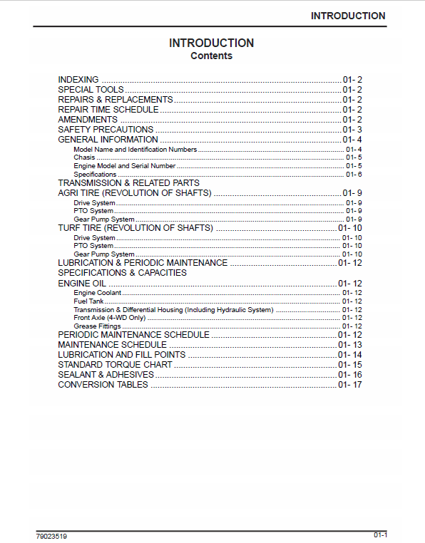
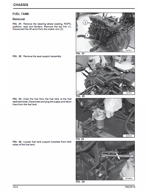
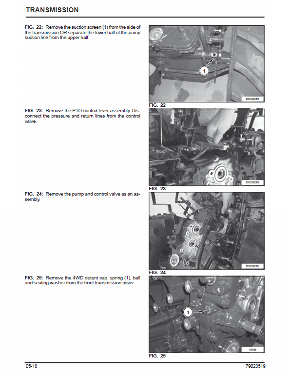
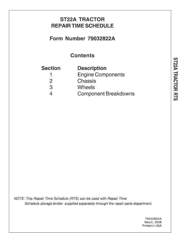
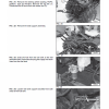
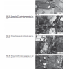
The introductory material identifies lubrication points, fluid-capacity references and scheduled maintenance before the component procedures begin. Chassis photographs follow the fittings around the fuel tank; transmission pages locate the suction screen and the pump-and-valve assembly controlling the implement drive. The companion Repair Time Schedule organizes labour operations for engine components, chassis, wheels and component breakdowns. It serves a different purpose from repair instructions.
Systems & Components Covered
- Identification and maintenance: Model and engine identification, capacities, lubrication points and periodic-service references.
- Chassis and fuel-tank access: Body fittings, tank connections and the illustrated removal sequence.
- Transmission and implement drive: Suction-screen access, pump and control-valve assembly, and four-wheel-drive selector components shown in the service pages.
- Workshop assembly references: Tightening tables, sealants, adhesives and special-tool information.
- Component service boundaries: Tractor-level procedures; the separate engine insert is referenced rather than represented as supplied internal-engine coverage.
- Labour-time schedule: Defined operations grouped by engine components, chassis, wheels and component breakdowns.
The Digital Workshop Advantage
The schedule can be consulted when identifying the labour operation, then the service PDF provides the illustrated working sequence. For example, the fuel-tank photographs identify connections that a time entry alone cannot explain. Maintenance tables remain a third type of reference, useful for checking capacities and service points without confusing them with dismantling steps.


Reviews
There are no reviews yet.